Have you asked the owner ?
...... I will test this PCB soon as possible ...... schematic from Suzy Jackson 🙂 post #21
Is there any other URL for post #21?
The schematic is not there anymore. Where is it now?
I suspect Suzy saw it, and asked Alex to take it down.
She is particularly bitter about commercial copiers of her circuit, and since there is no way of differentiating DIYers from commercial manufacturers, unfortunately she actively prevents promulgation of the schematic.
Fair enough, I say.
Hugh
She is particularly bitter about commercial copiers of her circuit, and since there is no way of differentiating DIYers from commercial manufacturers, unfortunately she actively prevents promulgation of the schematic.
Fair enough, I say.
Hugh
So we have a beautiful pcb designed by Alex_MM, and no schematic to comment about?
Don't you think a commercial manufacturer could reverse-engineer that pcb and get the schematic? Or google for it.
In fact that's what I did and I think I found it, taken from an '87 Australian Electronics Monthly mag. I haven't yet compared it all, but it very much looks like it, with all those ME340/350.
The output MOSFETs on Alex's are Exicon types, instead of SK134/SJ49.
Last edited:
Carlmart,
Yes, it's a pity on many levels. And you are right about a manufacturer reverse engineering it. Heck, you have yourself!
You cannot change someone's mind, particularly if they feel aggrieved.
The extent to which Suzy designed the amp, given it originally appeared in Electronics Today International from David Tillbrook (a Maths Professor from University of Sydney, BTW), is also debatable.
Alex does beautiful pcbs, no question. But there are lots of other designs around - many with his layout too - so it ain't all bad......
Hugh
Borbely's servo 50 , DC 102, and Millenium. All very good as his design skills and devices evolved.
Hi,
Waybackmachine to the rescue:
http://web.archive.org/web/20101030120623/http://www.littlefishbicycles.com/poweramp/
It should be noted that the design as such is not by Suzy, but adapted with minimal changes from David Tilbrook's AEM6000 design (something the original site clearly acknowledges BTW, in stark contrast to the habit of some here who routinely pass other people's designs off as their own, without attribution). So I kind of cannot see what Suzy is upset about.
As for the design itself, it is somewhat similar to the circuits by Lohstrom/Ottala/early Elektrocompaniet, but lacks the measures taken in the Lohstrom/Ottala to "broadband" the design. The output Fet's do not use any drivers with only around 10mA current available from the final VAS. Plus the selected semiconductors are mixture of poor linearity and poor availability.
So the open loop bandwidth and slew rate are compromised compared to what even much more pedestrian and simple designs can accomplish. So a lot of complexity without apparent performance improvements over more simple circuits, like the original Hitachi designs, due to a lack of optimising the topology for beast performance.
If we wanted something with Fet Input, there is an excellent design on page 150 of the Hitachi Application book, with more VAS current, simpler design and comparable or better THD Performance.
Ciao T
So we have a beautiful pcb designed by Alex_MM, and no schematic to comment about?
Waybackmachine to the rescue:
http://web.archive.org/web/20101030120623/http://www.littlefishbicycles.com/poweramp/
It should be noted that the design as such is not by Suzy, but adapted with minimal changes from David Tilbrook's AEM6000 design (something the original site clearly acknowledges BTW, in stark contrast to the habit of some here who routinely pass other people's designs off as their own, without attribution). So I kind of cannot see what Suzy is upset about.
As for the design itself, it is somewhat similar to the circuits by Lohstrom/Ottala/early Elektrocompaniet, but lacks the measures taken in the Lohstrom/Ottala to "broadband" the design. The output Fet's do not use any drivers with only around 10mA current available from the final VAS. Plus the selected semiconductors are mixture of poor linearity and poor availability.
So the open loop bandwidth and slew rate are compromised compared to what even much more pedestrian and simple designs can accomplish. So a lot of complexity without apparent performance improvements over more simple circuits, like the original Hitachi designs, due to a lack of optimising the topology for beast performance.
If we wanted something with Fet Input, there is an excellent design on page 150 of the Hitachi Application book, with more VAS current, simpler design and comparable or better THD Performance.
Ciao T
Hi,
Waybackmachine to the rescue:
http://web.archive.org/web/20101030120623/http://www.littlefishbicycles.com/poweramp/
It should be noted that the design as such is not by Suzy, but adapted with minimal changes from David Tilbrook's AEM6000 design (something the original site clearly acknowledges BTW, in stark contrast to the habit of some here who routinely pass other people's designs off as their own, without attribution). So I kind of cannot see what Suzy is upset about.
As for the design itself, it is somewhat similar to the circuits by Lohstrom/Ottala/early Elektrocompaniet, but lacks the measures taken in the Lohstrom/Ottala to "broadband" the design. The output Fet's do not use any drivers with only around 10mA current available from the final VAS. Plus the selected semiconductors are mixture of poor linearity and poor availability.
So the open loop bandwidth and slew rate are compromised compared to what even much more pedestrian and simple designs can accomplish. So a lot of complexity without apparent performance improvements over more simple circuits, like the original Hitachi designs, due to a lack of optimising the topology for beast performance.
If we wanted something with Fet Input, there is an excellent design on page 150 of the Hitachi Application book, with more VAS current, simpler design and comparable or better THD Performance.
Ciao T
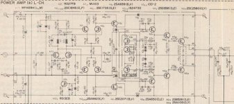
The schematic in your link is not exactly the good one.
The version found at DIY Audio has five pairs of output
devices with drivers added although they arel the crappy MJE340/350.
Also , compensation seems to be erratic but i didnt check with sims.
I ve got the schematic but since the author dont want it to be published
i wont upload it.
This schematic trace its origin in the Sansui Diamond topology below ,
with the slight difference that a differential complementary VAS has been
implemented instead of the usual complementary symetrical VAS as well
as cascoding the input differential.
Attachments
dear sir,
can anybody solve my problem.
i want pcb copper side of using two trans.2sk1058 and 2sj162.
thanks
can anybody solve my problem.
i want pcb copper side of using two trans.2sk1058 and 2sj162.
thanks
Hi,
That is the one Suzy published.
So, someone found a way to make a mediocre design much more expensive to build?
Possibly Sansui, hard to remember where I first came across it, I have seen it quite a few times. It is also seen in Accuphase gear.
I would consider Sansui's take actually a bit more intelligent, as they eliminate the need for tail CCS's and create the bipolar version of the Curl/Borbely input stage, which does have some additional benefits over using tail CCS's beyond component count.
Ciao T
The schematic in your link is not exactly the good one.
That is the one Suzy published.
The version found at DIY Audio has five pairs of output devices with drivers added although they arel the crappy MJE340/350.
So, someone found a way to make a mediocre design much more expensive to build?
This schematic trace its origin in the Sansui Diamond topology below, with the slight difference that a differential complementary VAS has been implemented instead of the usual complementary symetrical VAS as well as cascoding the input differential.
Possibly Sansui, hard to remember where I first came across it, I have seen it quite a few times. It is also seen in Accuphase gear.
I would consider Sansui's take actually a bit more intelligent, as they eliminate the need for tail CCS's and create the bipolar version of the Curl/Borbely input stage, which does have some additional benefits over using tail CCS's beyond component count.
Ciao T
...... I have new reborn QUAD 405 with 2 SK 1058 and 2 SJ 162 🙂 and schematic diagram ....
Alex
dear sir
plz send me its pcb.
dear masood ,
Sorry, but I have no PCB files from this amplifier , was made by factory 🙁
Regards Alex .
Sorry, but I have no PCB files from this amplifier , was made by factory 🙁
Regards Alex .
Amp Simulation
Hello Lineup,
which program did you use to simulate your 20 watt amp? Looks very attractive indeed.
Regards,
Michael
Hello Lineup,
which program did you use to simulate your 20 watt amp? Looks very attractive indeed.
Regards,
Michael
Here's one masood its a kit from futura elettronica http://www.futuraelettronica.net/pdf_ita/7100-FT15K.pdf
You should be able to trace the PCB layout from the pdf.
You should be able to trace the PCB layout from the pdf.
Here's one I will be building soon, beautifully designed with detailed design notes.
MJR7-Mk5 Mosfet Power Amplifier

MJR7-Mk5 Mosfet Power Amplifier
Here's one I will be building soon, beautifully designed with detailed design notes.
What's so good about it?
It does have a large output blocking capacitor, which I don't think is too good for sound quality.
Nelson Pass did design one of most built DIY power amps using an output cap, but I think it was interesting for using very few parts, not for a serious good sounding project.
- Status
- Not open for further replies.
- Home
- Amplifiers
- Solid State
- 2SK1058 and 2SJ162 amplifiers Collection