Is there a reason why CRC filters are almost never seen in a chipamp psu?
I have a handful of 3300uf caps, and am trying to determine if a CRC, for example 3300uf, 1R (or maybe .5R), 3300uf would be appropriate. ?
Of course, I could just omit the resistor and parallel the caps.
Any insight would be appreciated. Thanks!
I have a handful of 3300uf caps, and am trying to determine if a CRC, for example 3300uf, 1R (or maybe .5R), 3300uf would be appropriate. ?
Of course, I could just omit the resistor and parallel the caps.
Any insight would be appreciated. Thanks!
Most chipamp builders are looking for the least effort amplifier.
That means they will not research the project and will take the simplest offering.
The next group of builders will implement the full National guidelines increasing the component count by about 10 items.
The third group will look at best practical topology and combine it with best practical layout.
We are now down to the last few per thousand builders looking for any further improvement.
You don't see many going any further because builders this fastidious will have moved on to something better than a mass produced TV sound amplifier.
Knowing some of the shortfalls of the 3886, I reckon it is worth improving the PSU to get the best from a chipamp. But is it good value for the effort and the money you have thrown at it?
rC, rCRC, rCLC are all much the same to most folk.
Few realise the benefits that accrue from the extra filtering.
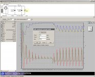
Do some PsudII and see what happens with the 50/60Hz.
Or move over to LTspice to examine the harmonics of the mains frequency that leak through to the chipamp.
One thing that I believe is worth pointing out: the last C of any PSU supplies most of the speaker current. The decoupling Cs (mid frequency and high frequency decoupling) supply the majority of the transient currents flowing through the speaker.
On that basis, 3m3F is not sufficient for a wideband amplifier.
That means they will not research the project and will take the simplest offering.
The next group of builders will implement the full National guidelines increasing the component count by about 10 items.
The third group will look at best practical topology and combine it with best practical layout.
We are now down to the last few per thousand builders looking for any further improvement.
You don't see many going any further because builders this fastidious will have moved on to something better than a mass produced TV sound amplifier.
Knowing some of the shortfalls of the 3886, I reckon it is worth improving the PSU to get the best from a chipamp. But is it good value for the effort and the money you have thrown at it?
rC, rCRC, rCLC are all much the same to most folk.
Few realise the benefits that accrue from the extra filtering.
Do some PsudII and see what happens with the 50/60Hz.
Or move over to LTspice to examine the harmonics of the mains frequency that leak through to the chipamp.
One thing that I believe is worth pointing out: the last C of any PSU supplies most of the speaker current. The decoupling Cs (mid frequency and high frequency decoupling) supply the majority of the transient currents flowing through the speaker.
On that basis, 3m3F is not sufficient for a wideband amplifier.
Don't have a PC, can't use PsudII.
Not trying to find the last bit of performance, just trying to use up parts I have on hand.
Datasheet says to use 470uf or more at the pins. Why does BrianGT layout only use 100uf?
You are talking about the caps closest to the pins? 3300 isn't enough? I was planning on using 200uf, with film bypasses. I will replace those with 2200uf. (Again, it's what I have handy)
I'm more curious about the caps and possibly CRC after the bridges... Is there an agreed upon minimum? If I have bridge > 3300uf >.5R >3300uf, and then the 2200uf at the pins, is that sufficient if your opinion? (10000uf per rail) Or should the R of the CRC be eliminated and just parallel (2) 3300 per rail?
Not trying to find the last bit of performance, just trying to use up parts I have on hand.
Datasheet says to use 470uf or more at the pins. Why does BrianGT layout only use 100uf?
One thing that I believe is worth pointing out: the last C of any PSU supplies most of the speaker current. The decoupling Cs (mid frequency and high frequency decoupling) supply the majority of the transient currents flowing through the speaker.
You are talking about the caps closest to the pins? 3300 isn't enough? I was planning on using 200uf, with film bypasses. I will replace those with 2200uf. (Again, it's what I have handy)
I'm more curious about the caps and possibly CRC after the bridges... Is there an agreed upon minimum? If I have bridge > 3300uf >.5R >3300uf, and then the 2200uf at the pins, is that sufficient if your opinion? (10000uf per rail) Or should the R of the CRC be eliminated and just parallel (2) 3300 per rail?
I understand decoupling to be different from smoothing in the PSU.
I never swap these names to help avoid confusion.
Decoupling is placed at the current consumer to attenuate the change in voltage as the client changes current demand.
These are usually:-
a.) medium frequency decoupling. I suppose anywhere from 10uF upto 470uF would do for this.
b.) high frequency decoupling. Anywhere from 10nF to 1uF depending on circuit speed/slew rate.
Smoothing is placed at the rectifier in the PSU.
The LAST smoothing Capacitor (in the PSU) supplies the low frequency current to the speakers. As such it is not hindered significantly by a little inductance due to connecting wires from PSU to amplifier.
Ok, thanks for the clarification. I will keep the 200uf electrolytic and .1uf film that are on the PCB.
To some it is a matter of diminishing returns. Each further filter stage makes less of a sonic improvement (depending on what was lacking/design in general).
The true test is design it so there is a place for your R between the caps and audition it both ways. If the R doesn't help it sound better then put a jumper wire there.
The true test is design it so there is a place for your R between the caps and audition it both ways. If the R doesn't help it sound better then put a jumper wire there.
I always had the same question... seems all implementations are special kind of CRC where R is just the resistance of cable between PSU and chip's board = 0,01 ohm 😉Is there a reason why CRC filters are almost never seen in a chipamp psu?
On my Audiosector LM3875 amp, I have 1000uF at PSU + 1Ohm + 1500uF at chip's board, it works fine with a Fostex FE168Ez but I never tested on heavier multiway loudspeakers...
A psu2 simulation shows differences beetween C1 and C2 for sure, but does it really make a difference for the chip's sound, that is the question and as [ ! ] said, it is still possible to shunt R to test...
Attachments
Last edited:
On my Audiosector LM3875 amp, I have 1000uF at PSU + 1Ohm + 1500uF at chip's board,
Do you have a photo of how you implemented that? I'm curious.
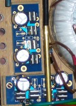
6L6, in fact you remind me it was not so easy to install the caps (1000uf / 63V / 105°C) at the PSU, as Audiosector boards are not made for that !
I had to tweak a little bit (dont remind how exactly) and caps are too close to the diodes but its not a real problem, diodes never go warm...
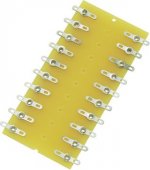
For R => 2 x 2.2 Ohm (2 Watts metal) in // on a piece (barrette ?) as you can see below :
I had to tweak a little bit (dont remind how exactly) and caps are too close to the diodes but its not a real problem, diodes never go warm...
For R => 2 x 2.2 Ohm (2 Watts metal) in // on a piece (barrette ?) as you can see below :
Attachments
The CRC resistors are on the PSU board?
With the Peter Daniel PCB the big caps are supposed to go on the bottom...
Which makes for new and diferent problems mounting them.
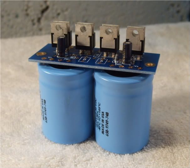
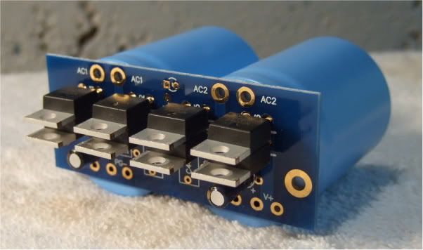
Those are 10,000uf 50V caps.
With the Peter Daniel PCB the big caps are supposed to go on the bottom...
Which makes for new and diferent problems mounting them.
Those are 10,000uf 50V caps.
You forgot the group who thinks 1500uF is a suitable value for a power supply cap because "It sounds better with less energy storage" or some such nonsense.Most chipamp builders....
The next group of builders...
The third group...

CRC sounds like a good idea to me, especially with separate RC for left and right channels.
yeah, I have seen many gainclone builders using 10uf in the power supply. I find it a joke!!! I did build a gainclone long time ago and I try those 10uf caps and it was ridiculous. at the end I finished using 20.000uf per rail and there was a BIG improvement.😉
The CRC resistors are on the PSU board?
With the Peter Daniel PCB the big caps are supposed to go on the bottom...
Which makes for new and diferent problems mounting them.
Those are 10,000uf 50V caps.
Hi 6L6,
Where did you place the resistor in Peter's PS board when implementing the CRC filter?
Thanks
Most any chipamp like LM3886 and TDA7294 have ridiculously bad PSRR on the -ve rail. The only simple way to get around this is to neither have any supply ripple nor any rectified load current ripple on the -ve rail.
Analog Devices app note AN202, fig.7 is the key how to achieve this, to "nail down" the input common mode voltage and keep it clean (that is, no components involved which are NOT linear copies of the signal current and voltage). This maintains that load current is pretty much the only current that the coupling capacitor ever sees except for the "0V bias" current, and any drop along its impedance is fully correlated to the signal.
Note that the "signal common" (== input and output reference) must NOT be connected directly to 0V (center tap) of the supply, instead a medium valued resistor should be used, 10x the DC speaker impedance is a good starting value (gives 10x offset voltage for the 0V imbalance, which is irrelevant). You can't DC-couple such an amp (the 0V will shift by the I*R drop), but that's not needed for audio anyway. Also, you can't use speakers that are AC coupled (yes, some are, internally) as the amp will then act as an integrator, locking to either rail after some time.
Bacically, it's very much like a single supply concept, but the "output capacitor" is inside the feedback loop and isn't charged through the load to reach mid-supply.
The 0V<--> -Rail cap, as well as the +Rail <--> -Rail cap must have the full rail-to-rail voltage rating, and you need a protection diode to prevent a destructive back-power event during power down.
CRC or RCRC can be used with good effect on the +Rail decouplers, but the 0V decoupler should be "one solid brick" of capacitance with low ESR and ESL.
When using this method, size and choice of capacitors has much less impact on sound than with standard split supply. Especially with the LM3886 the somewhat "grainy" signature of MF/HF is gone, IME.
And ff you ever have trouble getting (big) capacitors close to the point of load, used coaxial cable to span the distance, 30cm (1ft.). And, most important, make yourself absolutly clear that you know your current loops and minimize their geometric area.
1500uf is an optimal value if you use the amp with sensitive enough drivers. On my back-loaded Fostex FE168Ez in a small room I generally don't need more than 0.1 watt, where is the nonsense?You forgot the group who thinks 1500uF is a suitable value for a power supply cap because "It sounds better with less energy storage" or some such nonsense.
Now, if you own a 86dB 3 ways loudspeaker and you need loud bass, 10000uF or more per rail will be more suited for sure... you adjust the energy of the amp according to the drivers you use, this is the essence of DIY, no?
10uf at PSU is a really small value who can generate very fun oscillations on PSUDesignerII simulations, just try CRC=10uf+0.01Ohm+1000uf... but is this soft so accurate ?yeah, I have seen many gainclone builders using 10uf in the power supply. I find it a joke!!! I did build a gainclone long time ago and I try those 10uf caps and it was ridiculous. at the end I finished using 20.000uf per rail and there was a BIG improvement.😉
It seems cheap chipamp PSU way has perverted the old rules of CRC or CRCRC... normally the first capacitor is the smaller, but not so small, perhaps 1/5 to 1/2 of the following caps.
Personally, I prefer to keep the 10uf for decoupling at chip board, as per National Semiconductor specifications in LM4780 pdf :
Attachments
Last edited:
Hi 6L6,
Where did you place the resistor in Peter's PS board when implementing the CRC filter?
LOL... I didn't... That photo is only for illustration of the caps mounted from the bottom. They are not even soldered. 🙂
- Status
- Not open for further replies.
- Home
- Amplifiers
- Chip Amps
- CRC Chipamp psu