scitizen17 - sending PM. I like the chassis that you built. My metal working skills probably wouldn't be up to steel though.
The steel chassis I used was by way of what I had available. I would not recommend it if you had a choice. Very difficult to deal with. But hey, at the end of the day, it worked.
It is important to note that if building the 100W version, R8, R9, R10, R11 should be changed to around 470R at 2 watt. Change R29, R30, R31, R47 to 220K-3W. If you wish, there is a 2000V 820 pF cap on Mouser for C7, C9, C10, C15: DEHR33D821KA3B Murata Ceramic Disc Capacitors
Check out this post if using 6HJ5: http://www.diyaudio.com/forums/tubes-valves/151206-posted-new-p-p-power-amp-design-35.html
If you look at the datasheet for the stock tube pin-out compared to the 6HJ5 it will be clear as to how it is to be connected if you refer to the Millett schematic.
When I was soldering R8, R9, R10, R11 I had originally put them in the original spot and cut the leads off before I realized that they needed to be repositioned for the 6HJ5's. The leads are too short to resolder. Since I don't have much of an electronics stockpile I am working on a Mouser order for the new resistors an a couple of other parts (shipping is starting to add up). I will double check on R29, R30, R31, R47. I have left out C7, C9, C10, C15 from something that I think George had posted. I'll check on that as well.
When I was soldering R8, R9, R10, R11 I had originally put them in the original spot and cut the leads off before I realized that they needed to be repositioned for the 6HJ5's. The leads are too short to resolder. Since I don't have much of an electronics stockpile I am working on a Mouser order for the new resistors an a couple of other parts (shipping is starting to add up). I will double check on R29, R30, R31, R47. I have left out C7, C9, C10, C15 from something that I think George had posted. I'll check on that as well.
Shipping does add up unfortunately. Just extend the leads, it will probably be OK. Buy another entire complement of parts while your at it. Who knows? you might build another one. The 220Ks (R29, R30, R31, R47) do need to be upgraded to handle the higher voltage transients. I have encountered no problems using the 820pF caps suggested, however leaving them out will not be audible I would think.
Shipping does add up unfortunately. Just extend the leads, it will probably be OK. Buy another entire complement of parts while your at it. Who knows? you might build another one. The 220Ks (R29, R30, R31, R47) do need to be upgraded to handle the higher voltage transients. I have encountered no problems using the 820pF caps suggested, however leaving them out will not be audible I would think.
I checked and did install the 3 Watt R29, R30, R31, R47. I remembered that when I placed the Mouser order I hadn't read all of the info on using 2 transformers with the FWB's so I didn't order the UF4007's, the large uF caps, or a way to temporarily connect it all together. The second build idea would make shipping more reasonable.
I've ordered all of my parts now except for coupling caps and a power transformer. I think I have a scavenged Sansui 45-0-45 that would work for the bias supply. Can anyone comment on the bit below and help me make sure that I'm on the right track in choosing a power transformer? I'd like to get close to 450V B+ but certainly would rather undershoot than overshoot.
I have played with PSUD and am using it to half-arsed guestimate what secondaries I want to end up with around 450V B+. Am I right that it is around 360V?
If I understand correctly (and I may not) I need a power transformer that can manage about 400ma of high voltage and better than 6A at 6.3V, yes?
If this is correct then it looks like the Antek AS-4T360 would do?
Sorting through all the Edcor offerings I'm not entirely certain which would be best -- would the XPWR143-120 do?
I used a pair of 470uF 400 Volt caps that I ripped out of an old server power supply. They work fine too.
TEAPO, United Chemiicon brands are rated at 105*C, recycled from computer-server psu's....
I've ordered all of my parts now except for coupling caps and a power transformer. I think I have a scavenged Sansui 45-0-45 that would work for the bias supply. Can anyone comment on the bit below and help me make sure that I'm on the right track in choosing a power transformer? I'd like to get close to 450V B+ but certainly would rather undershoot than overshoot.
Im not sure which setup you are shooting for. 360vac = over 500vdc
Id shoot for a half amp power supply and 450vdc. that would be about 320vac. Yes you want gobs of heater current if you are going for the bigger tubes. its sick really when you figure its over 50 watts just to keep the tubes warm.
360vac = over 500vdc
Unloaded yes, maybe 510V. Loaded your looking at around 460V DC. In my experience only, which is only a few years. I use V AC x 1.28 to get loaded DC voltage, assuming the tranny is a good match for the load. PSUD will get you very close when you give it the tranny info, scary close even 🙂
Unloaded yes, maybe 510V. Loaded your looking at around 460V DC. In my experience only, which is only a few years. I use V AC x 1.28 to get loaded DC voltage, assuming the tranny is a good match for the load. PSUD will get you very close when you give it the tranny info, scary close even 🙂
My main concern was him using the red board without the booster power supply. So the entire board is seeing 450v or higher. If that is the case, how long is the 450v caps seeing 500v+? Its not an crc power supply, b+ is connected directly to the caps.
I wonder if he could do a cLc setup with a half amp rated choke and then use 360vac and "tune" to get his desired b+ after the amp is warmed up.
My main concern was him using the red board without the booster power supply.
The red board will live at 450 volts, but ALL the caps fed by the B+ supply must be rated for 500 volts since the B+ will be at or slightly over 500 volts at turn on before the tubes are conducting. 450 volts will increase the dissipation in the regulator Mosfets so they will need a good size heat sink.
360vac = over 500vdc.......Unloaded yes, maybe 510V. Loaded your looking at around 460V DC......I use V AC x 1.28 to get loaded DC voltage
The textbook VAC * 1.414 = VDC is only valid at no load. As the tubes warm up and start to draw current the voltage will drop. The true voltage on the transformer secondary is often not related to what the spec sheet says. Hammond made (includes Allied) transformers routinely provide about 10% over spec voltage even loaded above the specified ratings.
I use VAC * 1.1 to1.2 for a tube rectifier, and VAC * 1.2 to 1.3 for a solid state rectifier for a first guess. These assumptions are based on real measured secondary voltages, not what it says on the transformer label. It is also influenced by the actual line voltage AND the distortion of your power line voltage. My power line runs about 10% distortion, mostly flat topping (like clipping) which reduces the output voltage.
that would be about 320vac.
I use a Hammond 272HX in a Simple P-P amp. It is rated 300-0-300 VAC, but measures 325-0-325 VAC under load in the amp. The amp uses a 5AR4 rectifier and has a B+ of 370 volts. That works out to VAC *1.14 = VDC. I have seen about 405 volts with silicon rectifiers , but this makes cheap "EL84's" rather nervous, so I don't use it that way.
In a different experiment I have used an Antek 4T360 (360-0-360 VAC) with solid state rectifiers to run 2 Simple P-P boards at the same time. This provides 430 volts of B+. JJ EL84's can eat this without exploding.
I have an SSE using an Allied 6K7VG (Hammond made) It is rated for 375-0-375 at 150 mA. I am sucking over 200 mA out of it and I still measure 390-0-390 VAC. I get 435 VDC (1.12) of B+ with a 5AR4 and 465 VDC with silicon diodes (1.19). The B+ hits 535 volts with the solid state diodes at first turn on, then drops. It comes up slowly with the tube rectifier.
Im waiting for George's evil twin to show up with and all motor run cap version thats doing 600v on the red board alone 😵
Im waiting for George's evil twin to show up
Two big dumb blonde ones blowing up tubes.....that's a scary thought.
all motor run cap version thats doing 600v on the red board alone
I ran 600+ through the board once and saw the fire gods dance. That's when I figured out there must be a better way. 450 volts is probably the safe limit I would put on the board.
Upon further examination there are a couple of traces that are rather close for the current off board 600 volt configuration. The plate pins of the output tubes can see 1300 volts or more if you run it into clipping. One of the traces leading to the feedback resistors runs close to other stuff.
I have run the board for a few hours at 650 volts externally supplied, but decided that was the limit. Experiments at higher voltages will wait for better hardware......coming soon.
I'm still not sure how much current capacity my secondaries need to handle if I'm running at 400-450V. Can anyone tell me and ideally tell me how I would figure it out for myself?
I've already ordered my caps so I think I'll just go for something close to 320V primaries so that I don't push it with the caps.
I've already ordered my caps so I think I'll just go for something close to 320V primaries so that I don't push it with the caps.
I'm still not sure how much current capacity my secondaries need to handle if I'm running at 400-450V. Can anyone tell me and ideally tell me how I would figure it out for myself?
I've already ordered my caps so I think I'll just go for something close to 320V primaries so that I don't push it with the caps.
Id use a light bulb bank and a good thermal probe. Keep increasing the load till the outside of the transformer hits about 55c. That would be your current rating. Not sure what you would use as a direct ac load at 300-400v. You figure your shooting for a half amp at 400+ v, aka 200 watts. a light bulb runs at 120vac, so triple that, 360vac. so 3 75 watt bulbs in series?
I'm still not sure how much current capacity my secondaries need to handle if I'm running at 400-450V
I am assuming you need to buy a power transformer and you want to know which one. Tell us which output tubes you plan to use, and how much power you expect (or want). Do you have OPT's yet? If so, what impedance?
Id use a light bulb bank and a good thermal probe. Keep increasing the load till the outside of the transformer hits about 55c. That would be your current rating. Not sure what you would use as a direct ac load at 300-400v. You figure your shooting for a half amp at 400+ v, aka 200 watts. a light bulb runs at 120vac, so triple that, 360vac. so 3 75 watt bulbs in series?
I guess I'm kinda confused here. I am wondering how much current the power tubes will draw.
I am assuming you need to buy a power transformer and you want to know which one. Tell us which output tubes you plan to use, and how much power you expect (or want). Do you have OPT's yet? If so, what impedance?
Yes, that it what I want to know!!
I have a bunch of 6GV5 and some 6GY5.
Iron is from a Knight integrated that had a 5-20 circuit (more or less). I figure the iron can do 40W fairly reasonably and maybe a bit more. It has 6.6K primaries.
Thanks for the guidance. I was putting more time into studying how these things work before I had I job. Now I have a job which means that while I have the few extra bucks to buy the parts I have far less time to spend learning about how amplifiers work.
I am assuming you need to buy a power transformer and you want to know which one. Tell us which output tubes you plan to use, and how much power you expect (or want). Do you have OPT's yet? If so, what impedance?
Perhaps I have been trying to make a simple thing hard. Is it as simple as P = E * I? In which case I would likely be fine with something on the order of 200ma, yes? or would that be cutting it too close. At any rate it looks more and more like Antek. AS-4T320, AS-2T300 or AS-1T300.
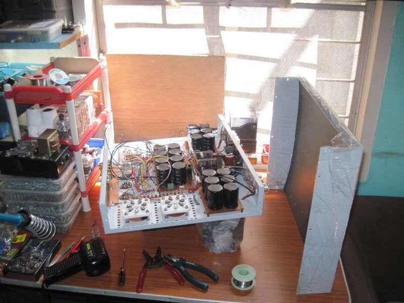
My board and Mouser parts got here today. As soon as the kids were in bed I stuffed all the resistors and diodes in.
Last edited:
You tell us the tubes and power output you are looking for. Then we can give a rough guess on the power. We know you are shooting for 450v. At stock output transformer load thats only 25 watts a channel. Drop in some 6Hj5 tubes and 3.3k output transformers and you are looking at alittle over 60 watts.
This might help too:
http://www.hammondmfg.com/pdf/5c007.pdf
A good rule of thumb for this build is to have your power supply at least the same as your output power. This would be fine unless you are playing sine waves into both channels all day🙂
So if you are shooting for lets say the limit of the stockish tubes, 450v and 5k-6.6k load of about 40 watts. That would be a good number for your 200ma.
You tell us the tubes and power output you are looking for. Then we can give a rough guess on the power. We know you are shooting for 450v. At stock output transformer load thats only 25 watts a channel. Drop in some 6Hj5 tubes and 3.3k output transformers and you are looking at alittle over 60 watts.
This might help too:
http://www.hammondmfg.com/pdf/5c007.pdf
A good rule of thumb for this build is to have your power supply at least the same as your output power. This would be fine unless you are playing sine waves into both channels all day🙂
So if you are shooting for lets say the limit of the stockish tubes, 450v and 5k-6.6k load of about 40 watts. That would be a good number for your 200ma.
Thanks. That lines up with what I was guesstimating. I have two sets of output iron I can try actually. One is 4.4K from a 7355 PP (not UL if that matters) and the other is 6.6K from Mullard 5-20 circuit. As you might expect the latter set of iron is a bit larger. The more I cogitate on it all the less hung up I am on maximum power and more curious about which set would actually sound better. I can always build another, more powerful amp after this one if I feel the need to. That said, I see no point in not extracting as much as I *reasonably* can from what I have. I figure the 6.6K iron is good for 40W per channel and the 4.4K iron for 30W per channel. I know that the voltage I would want to use with each set would be different. I think I could almost use the transformer specified in the BOM with the 4.4K iron. I might even get two power transformers so I can try both. I dunno. This is as much about learning and experimenting as finishing an amp.
I suppose what I really should figure out is just how you guys are estimating the power output from the amp given the voltage and output impedance. Is it more a matter of observation or derivation from published data (data sheets) or both?
FWIW - The 4.4K iron is from a HK A500 and was made by Magnetic Windings and the 6.6K iron was from a Knight KA-95 and was made by one of the lesser known companies in Chicago that was subsumed by Northlake many years ago.
- Home
- Amplifiers
- Tubes / Valves
- Posted new P-P power amp design