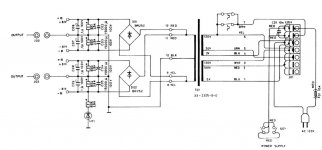
I'm looking for a new amp project that can use an existing chassis and power supply. The amp in question is a dead Adcom GFA-555 which has some nice heat sinks and about 60,000uf of power supply capacitance. The problem is that is has 81V rails (PS schematic attached), which exceeds most of the projects I've seen here. The power supply has tested well, and seems to be capable of reuse.
I've found the thread http://www.diyaudio.com/forums/pass-labs/64226-plh-retrofit-hafler-adcom.html that specifically mentions re-using an Adcom GFA-555 but it seems to have petered out. I'd like to try an F5 amp (from the Pass Labs forum) but my high rail voltage seems inappropriate for it.
I'm hoping for a project that has a good cost/performance ratio as my SE 300B project is consuming most of my hobby funds. At the very least I want something that sounds as good pr better than a stock GFA-555, however.
Please suggest applicable projects and/or workarounds for my high rail voltage.
Thanks!
p.s. The completed project will be hooked up to a pair of stock Tri-Trix speakers (nominally 8 ohms) in a large-ish basement. Bass is handled by a dedicated sub-woofer. Fairly low volume levels are acceptable. Primary music will be rock with some techno and solo-female-vocalists.
Attachments
There is an chip amplifier capable of more than 100W called "STK4044" series, but at 71V, and are easy of build. Try some more voltage IC.
Just thinking aloud without really thinking 🙂
You're on 120V ? Amp can be used on 240V and looks to have a good selection of tappings. So wire the tranny for 220 or 240 and that will give correspondingly lower output voltage.
You're on 120V ? Amp can be used on 240V and looks to have a good selection of tappings. So wire the tranny for 220 or 240 and that will give correspondingly lower output voltage.
Both excellent advice!
I see that Digi-Key still has the LM4702 in stock. I'll see if I can find any listening impressions with that chip.
Mooly, will wiring for 240V input give me 1/2 output (120 to 81 vs 240 to 40.5) or is there a conversion factor?
Thanks!!!
I see that Digi-Key still has the LM4702 in stock. I'll see if I can find any listening impressions with that chip.
Mooly, will wiring for 240V input give me 1/2 output (120 to 81 vs 240 to 40.5) or is there a conversion factor?
Thanks!!!
Both excellent advice!
I see that Digi-Key still has the LM4702 in stock. I'll see if I can find any listening impressions with that chip.
Mooly, will wiring for 240V input give me 1/2 output (120 to 81 vs 240 to 40.5) or is there a conversion factor?
Thanks!!!
No conversion factor... it's as GloBug says.
I would assume at half the power, i.e. the same secondary ampere, dictated by the thicknes of the wire ?
Best regards
Ebbe
Best regards
Ebbe
The amp in question is a dead Adcom GFA-555 which has some nice heat sinks and about 60,000uf of power supply capacitance. The problem is that is has 81V rails (PS schematic attached), which exceeds most of the projects I've seen here. The power supply has tested well, and seems to be capable of reuse.
Probably a stupid question but: why not repair the dead Adcom?
The 81V rails are good for about 400W into 8ohms. This would be quite a project.
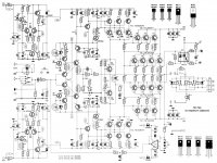
Something like this perhaps?
Trouble is, it 'only' uses 70V rails.
Something like this perhaps?
Trouble is, it 'only' uses 70V rails.
Attachments
Last edited:
I believe you are at advantage with such high rails.
There is alot of choice , really.
Just on top of my mind,...
If you want field proven designs, have a look of APEX threads about 500 W amplifie with limiter. This is with BJTs.
If you use good ONSemi ones there is no fear of 80V whatsoever, assuming that you implement enough pairs to fulfill the Current (A) needs.
Such high(er) rail is normally good for MOSFETS, that tend to loose something on the swing.
If you want something straightforward, there is a "the Wire" project with a LM 49830 and lateral FETS. It is supported by a National Application Note, sort of warranty of result.
Otherwise you could get involved in something more sophisticated and experimental, like the Workhorse VFET project (that , BTW could give you more power for the Volt since output it is almost rail-to-rail).
Doctor Bora also should have some FET proven design for your needs.
If you want something with a ready PCB, there is the P101 from ESP, another rugged design with Laterals.
I am sure I forgot a lot of other good DIY projects (my apologies to the authors), but, as you see, you can really choose.
I would certainly go with wiring the primary for 240V operation which will give you 40V rails.
Still high for a basic F5 though.
Have a look at http:\\www.kk-pcb.com There you will see a few variations of the Pass series and the different rails that they use.
Do bear in mind that the Pass amps generally use ABSOLUTELY MASSIVE heatsinks, not just big sinks.
Have a look at http:\\www.passdiy.com and the DIY gallery to see a few examples.
Correct me if I'm wrong here as Im not 100% certain. In the basic transformer equation we calculate Np (the primary turns) using an agreed maximum flux density for the core.
If you decide to increase the primary turns you are simply wasting wire or reducing the maximum flux density in the core, this is not an issue as the windings are doing the work instead of the magnetic material of the core. With enough windings you can make a transformer with no core at all.
Therefore doubling the number of primary turns (is using 240 windings instead of 110) will just make the core run cooler as it's doing less work.
What I'm not clear about is how the thinner 240 primary winding might cope with the increased primary current. Is a transformer manufacturer going to wind the 110 portion with thick wire and then continue on with thinner wire for the additional turns. Personally I think NOT. At a reasonable guess the whole primary winding would have been done in a single session with the same wire. HOWEVER, in the commercial world, if you can save 10 cents per unit in a production run of millions - it might be worth the scrimping.
Last edited:
That is an Elektor project. I am not sure they are so reliable. Be careful.
Look for that specific project on this forum and see what people say.
Once again: why not repair or clone the Adcom 555?
Look for that specific project on this forum and see what people say.
Once again: why not repair or clone the Adcom 555?
I'm not sure where the Adcom fits into the Hi-Fi market. It's not commonly known here in the UK.
If its a good amp then why not clone or repair it.
If its a good amp then why not clone or repair it.
Forget the STK chips - they are long obsolete and you're only using old stock getting them. Besides which, they are not that reliable.
For this sort of thing, MJ21193/4 output transistors will probably be ideal.
For this sort of thing, MJ21193/4 output transistors will probably be ideal.
Carlmart, I would absolutely love to fix the Adcom. However, as with most things, there is a short story there. This amp is actually the catalyst that got me into DIY audio. I received it from a co-worker for free, but with only one channel working. After hearing how good the one channel was, I decided to fix the bad channel. I spent weeks unsoldering leads and testing every single component (and I found quite a few that were bad). I got my parts list together and ordered everything I needed (except I couldn't find any of the output transistors; so I had to settle for substitutions). Over the months that followed, I read everything I could find on the GFA-555. Finally I was ready to test my repairs. It ended in failure. I still don't know why. Then, I committed the ultimate sin. By accident I fried the good channel, which was my only reference for a working amp. So now I'm sick of the whole damn thing, and am about ready to burn it on a funeral pyre. That's when I had the idea that I might could make it live again by re-using the chassis and power supply. I've built several projects since then, and have had no problems. So my construction and direction following skills are ok. It's my troubleshooting skills that are whacked. I plan to keep the Adcom parts, and who knows... Maybe in 30 years I'll be ready to try again.
Effebi, thanks for the plethora of ideas! Great information there. I really like the ESP P101, and having a PCB is a definite plus. The APEX amp looks like it's more of a PA system, which doesn't interest me much. I have seen "The Wire" thread, but I guess I missed the voltage range. I'll re-read the thread, as it does sound tempting. I'm not familiar with Doctor Bora (apologies to the good doctor), can you point me in a direction?
KatieandDad, Thanks for the link to kk-pcb; good stuff there! I see what you mean about the heat sinks. I was thinking I could get away with the Adcom heat sinks and some active cooling with a small fan, but now I'm not sure if that would be enough. I do love the low parts count of the Pass designs. I can't comment on the transformer windings. Perhaps more information will appear on this thread.
Carlmart, Which project is an Elektor project? I am a fan of reliability, of course.
Thanks All!!!!
Carlmart, Which project is an Elektor project? I am a fan of reliability, of course.
This one is:
http://www.diyaudio.com/forums/solid-state/205341-seeking-project.html#post2885344
The Apex seems like a good DIY project, and it's regulated, so you can probably use the +/-81v you have. The designer is on the thread, so you can ask him what to do for higher voltages.
- Status
- Not open for further replies.
- Home
- Amplifiers
- Solid State
- Seeking a project