@ wolfsin.. lol, had a proper belly laugh at that 😀
Thanks for the advice everyone, the signal inputs are isolated from the case. I'll try connecting the potentiometer's body to signal ground first, then go from there 🙂
Thanks for the advice everyone, the signal inputs are isolated from the case. I'll try connecting the potentiometer's body to signal ground first, then go from there 🙂
The Wire on the Chopping Board...
... will it make the cut or go to the Classifieds?
Sounding very promising so far on this patchup. Great work, Owen and thanks for sharing!
Next up - give it an optical volume control (LDRs). I know a guy with an Audeze LCD-3 itching to have a taste 😉
... will it make the cut or go to the Classifieds?
Sounding very promising so far on this patchup. Great work, Owen and thanks for sharing!
Next up - give it an optical volume control (LDRs). I know a guy with an Audeze LCD-3 itching to have a taste 😉
Bernie7, looking very good, is that one of the original psu's?
I'm trying to decide between getting some LCD-2s or HiFiMan HE-500s. Having some Sennheiser HD650s already, I'm leaning towards the HE-500s.
Eveyone, thanks again for the advice re' sytem buzz/hum... connected a small wire between signal ground and the potentiometer's body, problem 100% solved 🙂 also added some heatshrink to the iec terminals...
Last edited:
Bernie7, looking very good, is that one of the original psu's?
No, it's with my own parts built to (mostly) Owen's specs.
I suspect pots will be the limiting factor for this ultra design. A Lightspeed-type attenuator should show how close this 'Wire' is to the ideal 'wire with gain' 🙂
... will it make the cut or go to the Classifieds?
Sounding very promising so far on this patchup. Great work, Owen and thanks for sharing!
Next up - give it an optical volume control (LDRs). I know a guy with an Audeze LCD-3 itching to have a taste 😉
optical volume control? thats often some pretty high distortion right there. a quality stepper (doesnt have to be top shelf and you can find the positions you use most and use high spec resistors there) will only add very negligible distortion, optical control solves a couple of problems, but brings a raft of its own. if you are looking for low distortion, the lightspeed is not the place to look. i researched optical volume and even have a couple of the lightspeed pcbs here, but after looking into it further i found out the reasonably high distortion they add. It sounds like a great idea, but the reality is different thing altogether. I suggest you do a bit more reading, i'll see if i can find the posts. read Nelson Pass's comments on it for example, here on the forum. thats even when you have matched the leds
Last edited:
here's a thread over at another forum that discusses the downsides and distortion is a MAJOR one. best case 0.1% with the series/shunt type like the lightspeed (0.02% with the higher spec and only shunt) and thats with 2v across them with NO attenuation, so this is just the distortion of the LED, turn the volume down, you get magnitudes higher distortion (like 0.74%!! and its neither linear nor even mostly second harmonic.
many still report great sound, but personally i would find it irony itself to build the wire and add an optical volume to it. if you must, there is a better schematic that Nelson posted after posting the highly controversial measurements (you get heaps of hits when you type in lightspeed and nelson pass) here on the forum and it includes an integrated jfet buffer. the distortion stuff isnt even taking into account the fact they dont play well with low source impedance, or particularly low input impedance of the amp minimum 47K it has to be, the wire is nowhere near that, but you could modify it.
heres papas schematic; but note he still doesnt really recommend it, he just posted it as a better alternative after posting the dodgy numbers
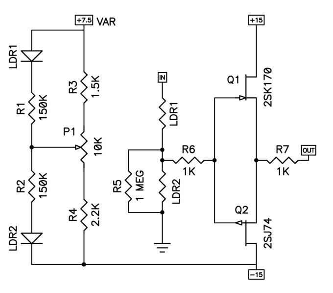
Last edited:
I will repeat, it does get good reports, but its not because of low distortion/high transparency. i didnt mean the above to be as inflammatory as it reads, but please do read up some more. i went to edit the above to get rid of the caps and change the tone, but was too late
Qusp, have you built and heard a Lightspeed or its variants (Lighternote, Warpspeed) for yourself?
Irrc George has measured and published THD figures less than 0.01% in the Lightspeed thread. We know that it doesn't sound as good when input exceeds 2V but this is rarely the case in actual use.
Irrc George has measured and published THD figures less than 0.01% in the Lightspeed thread. We know that it doesn't sound as good when input exceeds 2V but this is rarely the case in actual use.
Uh oh...my Wire is smoking!
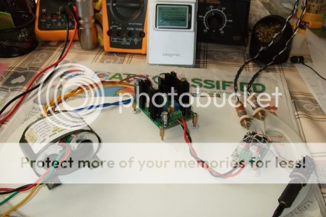
After 2 hours of playing fine music, smoke from the SE-SE board. All connections and parts checked out ok though. The Wire was still connected as pictured in previous page, with a portable Creative music player providing signal and volume control.
Suspected a blown 49600, but on closer examination today with all inputs and outputs removed except power, I saw the output ground connection point on the side of the V- making small sparks and leaving a small burn mark 😱 The nearest components - a 49600 and 330uf cap are correctly mounted. The other channel is fine.
I've resoldered the ground point with nothing on it now, but the sparking continues when power is on. I'm puzzled, why a ground connection and why this one? Owen is there some layer underneath to account for this behavior?
The music continues to play on this channel, but there's electrical noise as can be expected from the sparking.
Hi Bernie,
That is exceedingly strange! I have no idea what would be causing an actual arc on your board. Can you take a picture of exactly the spot where you're having the issue?
Looking at your picture, I would suggest the following:
1. Your standoffs look too big for the mounting holes and pads. They are designed for #4 hardware and if you used anything larger you could short the top power plane to the bottom power plane through the hardware.
2. If you happened to damage the soldermask on the top layer and then somehow flow solder overtop then you could potentially get a short from the solder to the top or bottom plane.
Can you also double check your rail votages? If you're running +/-15V then you would need an incredibly small gap to cause an arc at such a low voltage.
Let's see if we can get it sorted out... I would refrain from running it until we get to the bottom of it!
Cheers,
Owen
Perhaps output ground should not be touching the ground plane and the soldering caused a short, but the clearance is so little. I'll remove as much solder as possible and scratch at the ground plane to give it a bit more clearance and see what happens.
Hi Bernie,
The top plane is connected to V- and the bottom plane is connected to V+. The GND plane is on the inner layer, and the output GND is connected to this inner plane.
If the solder is overhanging onto the top or bottom plane from this pad then you might indeed have an intermittent short. Clear as much solder off that pad as possible and examine it closely for any damage to the soldermask coating.
A picture would be a very good diagnostic tool!
Regards,
Owen
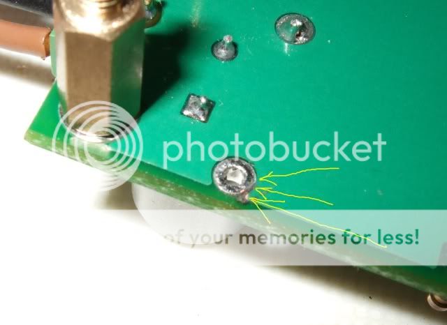
Owen, now that you explain the nature of the top and bottom planes, it makes sense why a short developed. I mounted a socket pin at the O/P ground and used more solder than I normally would have. After 2 hours of operation the soldermask coating gave way and we have the arcs developing at the places shown by the yellow arrows below.
The separation between the connection holes and supply planes is really a little too fine for comfort. Let this be an alert for future builders and let's hope there won't be reliability issues ahead.
To resolve my short I dug a trench around the grounding connection.
The separation between the connection holes and supply planes is really a little too fine for comfort. Let this be an alert for future builders and let's hope there won't be reliability issues ahead.
To resolve my short I dug a trench around the grounding connection.
glad you sorted out the issue, i think you'll find its a standard pattern, i doubt very much that owen made a custom part for a via and made the clearance smaller. He would also with a GB of this size have paid for checking at the board-house.
Hi Bernie,
Glad you got it sorted out! The clearances are indeed tight pretty much everywhere, and it does required a fair bit of caution while soldering. Usually the soldermask would prevent anything like that from happening, but all it takes is a small scratch or nick in the soldermask to allow a bridge. In a standard reflow process this would never be an issue, but it can be a problem while hand soldering.
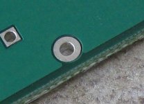
I checked all the boards I have here and I can confirm that there is not an actual problem with the PCB (no electrical short) and that the pad is centered in the clearance hole.
In the future, I will probably open up the tolerances a little bit to make life easier for everyone.
Cheers,
Owen
Glad you got it sorted out! The clearances are indeed tight pretty much everywhere, and it does required a fair bit of caution while soldering. Usually the soldermask would prevent anything like that from happening, but all it takes is a small scratch or nick in the soldermask to allow a bridge. In a standard reflow process this would never be an issue, but it can be a problem while hand soldering.
I checked all the boards I have here and I can confirm that there is not an actual problem with the PCB (no electrical short) and that the pad is centered in the clearance hole.
In the future, I will probably open up the tolerances a little bit to make life easier for everyone.
Cheers,
Owen
Attachments
tommy, do you think you could stop posting requests for pcbs everywhere? when owen is ready to start tallying up what spares he has he'll go through the thread and hand them out to those who posted first. posting repetitively will not make you any more likely to get some
- Home
- Amplifiers
- Headphone Systems
- "The Wire" Ultra-High Performance Headphone Amplifier - PCB's