yet i have not listend to a class D amp that sounds even remotely close to a class AB.
and when you look at the class D on your scope LOL.
and when you look at the class D on your scope LOL.
Does the capacitor filtered squarewave test mimic the short circuit output current?Simply not true. Power output into any purely reactive load is zero.
All heat generated by the output current must be dissipated by the
output devices. The purely reactive impedance limits this current.
Worst case is a dead short with peak currents and peak rail voltages.
This test illustrates how the protection works or blows up your amp.
That test does not blow up amplifiers. The test is designed to show the peak current ability into ultra low resistance loadings.
Class D amps don't dissipate more power with reactive loads, losses are the same as with resistive load at any output current. There are no SOA limitations in the output stage, as the switches are always either full on or full off. These are the major advantages of class D.
Furthermore, properly implemented current clipping gives class D amplifiers the ability to drive any load impedance down to 0 ohms without extra dissipation, only rms output current determines amplifier heating. Then, adding a long term rms current limiter makes the amplifier able to drive anything down to "screwdriver load" for as long as desired.
A pair of TO-220 outputs in class D can put as much power as four pairs of TO-264 bipolars in class AB (like doing +/-90V into 4 or 2 ohm).
Class D amps don't dissipate more power with reactive loads, losses are the same as with resistive load at any output current. There are no SOA limitations in the output stage, as the switches are always either full on or full off. These are the major advantages of class D.
Furthermore, properly implemented current clipping gives class D amplifiers the ability to drive any load impedance down to 0 ohms without extra dissipation, only rms output current determines amplifier heating. Then, adding a long term rms current limiter makes the amplifier able to drive anything down to "screwdriver load" for as long as desired.
A pair of TO-220 outputs in class D can put as much power as four pairs of TO-264 bipolars in class AB (like doing +/-90V into 4 or 2 ohm).
then why all those current limiters aren`t adjusted higher since
output stages can handle that?
It's something being continuously improved. Switching high currents fast is an order of magnitude more complex than making good class AB amps. I had the same feeling about existing stuff when I started to design class D. In response, I designed something with 80Apk and 32Arms capability that is now being produced and sold.
That current, whether average, or peak, or short term transient peak, comes from the amplifier decoupling and the PSU.
Not really. It's linear circuits where output and PSU share the same current.
In switched mode circuits they share (ideally) the same power, hence the name.
Dark,
I don't don't follow.
2nd sentence OK, 3rd sentence, you lost me.
Could you explain more fully?
I don't don't follow.
2nd sentence OK, 3rd sentence, you lost me.
Could you explain more fully?
Possibly I wasn't clear enough on what I was trying to say. Take 2:
An average current at the output of a power converter equals the current it consumes divided by voltage conversion ratio.
The result is input power is equal to output power if we neglect the losses, which is a first good approximation.
Take a step down buck regulator, which isn't that different from class D amp, it follows the rules above. That's why it is called power electronics even if it works over a fraction of a watt, while a 1kW linear class AB amplifier isn't 'power' electronic device by any standard.
Cheers
. Switching high currents fast is an order of magnitude more complex than making good class AB amps.
Aren't you addressing internal inductance of power transistors here?
A simple and elegant solution to this is called paralleling.
A simple and elegant solution to this is called paralleling.
No, paralleling = more power dissipated at bigger driver, and at more active mosfets. Difficult solutions is have different controlling on several mosfets in two group (low power group and high power group) or more, that each is may not always active. Since controllers are logics, there will be always fixed logic response. Easier solutions is playing with dynamic switching frequency.
edit:
note: I like more a tracking rails. Easy to limit the current for its maximum capability without entering any dagerous regions. Also very low power at idle, and 250mA biased class AB quality.
Last edited:
Tracking rails may help to alleviate class D fears, but it's just doing with a linear amplifier what you have not yet learned to do with PWM 😀
Driver losses increase due to paralelling is a non-issue, because you'd rather parallel smaller die devices in the place of one bigger one, resulting is roughly the same Qg while halfing parasitic inductances. The miller region provides the feedback nessesary to make the charge tolerances non-issue too.
Another approach is to have the half bridges interleaved, which is what I am currently working on. Not a trivial task to have both half-bridges self-oscillating and interleaved (bi-phase) at the same time if you were to ask.
Another approach is to have the half bridges interleaved, which is what I am currently working on. Not a trivial task to have both half-bridges self-oscillating and interleaved (bi-phase) at the same time if you were to ask.
Does the capacitor filtered squarewave test mimic the short circuit output
current? That test does not blow up amplifiers. The test is designed to show
the peak current ability into ultra low resistance loadings.
Hi,
Like I said I think its chasing numbers. The short test has to be pulsed
and very short term due to supply droop and the thermal limits of the
output devices, otherwise they will simply blow up.
What a published high number of peak current amps has to do with
sound quality is IMO next to irrelevant, but for sure a very low number
due to overzealous protection circuitry is not a good idea.
What I would say regarding say chipamps, their protection and their
impedance rating, is that they assume resistive loads, which gives
the lowest thermal stress which is the critical parameter in this case.
Real speakers, with reactance, require more thermal dissipation from
the amplifier. Realistically I'd rate a 4 ohm chip amp as 8 ohms, and
an 8 ohm chipamp as challenged with real 8 ohm speakers.
rgds, sreten.
Somebody correct me if I'm wrong, but one advantage of class D
is with reactive loads it can feed output current back into the
power supply, rather than dissipating it as output device heat.
A reactive load does not result in substantially higher dissipation in a class AB amplifier for "1st order loads" (RL, RC loads) because load impedance rises at the same time phase leads or lags. When phase is 45 degrees lagging or leading, current is already -3dB, so both effects tend to mutually compensate. The natural upper roll-off of speaker drivers, and the lower roll-off of low-Q LF alignments tends to be like that, rarely a problem.
To really stress a class AB amplifier, more L and C elements are required, there is no other way to demand substantial current out of phase with voltage. This never happens in active systems, and is only of concern in speakers with ill-designed passive crossovers and impedance dips, and high Q LF alignments, that don't sound good anyway because brief high energy transients get turned into longer lower energy ones.
To really stress a class AB amplifier, more L and C elements are required, there is no other way to demand substantial current out of phase with voltage. This never happens in active systems, and is only of concern in speakers with ill-designed passive crossovers and impedance dips, and high Q LF alignments, that don't sound good anyway because brief high energy transients get turned into longer lower energy ones.
I still can't make any class D with low phase shift at 10kHz, so I can't make current feedback with it to simulate reactive loads to input stage.Tracking rails may help to alleviate class D fears, but it's just doing with a linear amplifier what you have not yet learned to do with PWM 😀
Class D still needs more weapons to kill class AB😀.
Ok, class D is your world, you know more than me as I am much more in linear world.😉
She is talking switching high current faaast. If it is 1-5MHz, the driver may be hott.😱Driver losses increase due to paralelling is a non-issue.....
Interleaved self oscillation is a kick. They could turn on at same time when needed and turn interleaved in normal, and no fixed clock that makes some limitations to accuracy, less filter, less lagging.Another approach is to have the half bridges interleaved, which is what I am currently working on. Not a trivial task to have both half-bridges self-oscillating and interleaved (bi-phase) at the same time if you were to ask.
one advantage of class D is effficiency, no matter reactive load or not.... one advantage of class D is with reactive loads....
A reactive load does not result in substantially higher dissipation in a class AB amplifier
Hi,
Given your caveat is not always applicable the point is thus :
For an impedance load of 8 ohms, the more resistive the load the less
power dissipation is required in the amplifier and the more reactive the
load the more power dissipation is required in the amplifier. e.g. a 100W
amplifier driving 8R needs to dissipate that 100W in the output devices
if the load is 8 ohms purely reactive. The phase angle of a reactive load
indicates how more difficult the impedance value is compared to resistance.
For me its no big deal, just design a 8 ohm amplifier for 4R loads and a
4 ohm capable amplifier for 2R loads and that covers most real cases.
rgds, sreten.
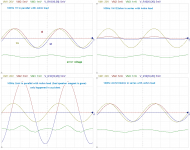
May be this voltage-driving class AB simulation will help. Normally inductor is series with resistor at loudspeaker, and if it has parallel model, it just when loudspeaker act like big microphone or generator from any accoustic reflection, small energy offcourse.
I am also simulating loudspeaker (parallel with 2mH) when one speaker short circuit and with crossover series or when its magnet block falling down to the ground by poor speaker accident😀.
I am also simulating loudspeaker (parallel with 2mH) when one speaker short circuit and with crossover series or when its magnet block falling down to the ground by poor speaker accident😀.
Attachments
For an impedance load of 8 ohms, the more resistive the load the less
power dissipation is required in the amplifier and the more reactive the
load the more power dissipation is required in the amplifier. e.g. a 100W
amplifier driving 8R needs to dissipate that 100W in the output devices
if the load is 8 ohms purely reactive.
This is a contrafactual hipothesis. The impedance of a nominally 8 ohm speaker can not be 8 ohm purely reactive. Not even close. There are rules for a real-life speaker impedance. This is what Eva talked about.
- Status
- Not open for further replies.
- Home
- Amplifiers
- Class D
- class D vs class AB current capability.