Thanks James! I was more worried about the extreme case damaging the headphones or the amplifier, not really the listener, which admittedly would happen first.
As it turns out, I've found a solution. I'm not sure I understand the problem, but that being said what I've done works and has little downside that I can see.
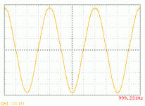
The issue cropped at at lower frequencies, higher impedance load, higher output voltage and cold heatsinks. For example, at 20kHz, 11 Vrms, 120 ohm load and cold heat sinks, the issue wasn't present. At warm heat sinks, 120 ohm load, 7 Vrms at 20 Hz the issue was present. As it turns out, 47nF + 22R seems to quiet it up at all combinations of hot and cold and frequency, up to my maximum voltage of 11 Vrms. There is a tiny bit of overshoot and undershoot on the square wave, but I'm not sure if that's some other test related anomaly.
I really wanted to up the gate and source resistors and play with that, but alas I see no reason to mess with that now, plus it's a pain to get to. The real question has to do with the resulting noise floor, which won't be effected by these changes now that things are stable.
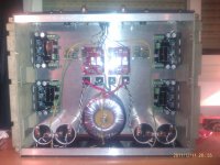
I also added 100nF caps across the bridge rectifiers and a 2uF-ish film cap on the PSU output, to no change in the PSU noise, which is now a solid 35mVAC @ 120Hz. I'm not sure what I was expecting, but regardless I'm not sure I can get any more low noise without chokes or lots of heat. I'm probably going to mill down my copper plate into a U and just go with that.
Next stop is the listening room. Over and out and all that. I'll report back though 🙂
As it turns out, I've found a solution. I'm not sure I understand the problem, but that being said what I've done works and has little downside that I can see.
The issue cropped at at lower frequencies, higher impedance load, higher output voltage and cold heatsinks. For example, at 20kHz, 11 Vrms, 120 ohm load and cold heat sinks, the issue wasn't present. At warm heat sinks, 120 ohm load, 7 Vrms at 20 Hz the issue was present. As it turns out, 47nF + 22R seems to quiet it up at all combinations of hot and cold and frequency, up to my maximum voltage of 11 Vrms. There is a tiny bit of overshoot and undershoot on the square wave, but I'm not sure if that's some other test related anomaly.
I really wanted to up the gate and source resistors and play with that, but alas I see no reason to mess with that now, plus it's a pain to get to. The real question has to do with the resulting noise floor, which won't be effected by these changes now that things are stable.
I also added 100nF caps across the bridge rectifiers and a 2uF-ish film cap on the PSU output, to no change in the PSU noise, which is now a solid 35mVAC @ 120Hz. I'm not sure what I was expecting, but regardless I'm not sure I can get any more low noise without chokes or lots of heat. I'm probably going to mill down my copper plate into a U and just go with that.
Next stop is the listening room. Over and out and all that. I'll report back though 🙂
You can change the quality of that 35mV on the power supply rails - I mean, there will be all sorts of small rubbish and spikes at quite high frequencies that will have an effect on the low signal level that'll be a lot more noticeable on the headphones - couple of things maybe worth looking at.....
Add an extra R-C on the supply and possibly reduce each capacitor value ...
After the diodes, add a specific "snubber" network (R-C & C) like on the Hagerman website.....
Use 2 diodes in series for each rectifier with a load sharing resistor - a la "E C Design" on the "Ultimate 1541A NOS Dac..." thread
Add a Cmultiplier after the existing C - R - C supply - a transistor version will only reduce rails by a volt, or so.......
Change the resistors on the amp board to lower noise ones - all of them - not a cheap exercise, unfortunately......
Not totally sure that the small amount of ripple will reduce the noise floor, even tho it seems logical, but when I changed the Roedestein resistors to PRPs, much quieter amp, but this might be because of the different nature of the resistors themselves - a bit of guesswork and another opportunity to indulge in favourite hobby of "power supplies playtime"!
😱
Merry Christmas!
Can't wait to see what kid of beast this is. So it is not clipping +/- 4V swing into 0.1 ohm - wonder what it will say to an 8 ohm load...
Merry Christmas!
Can't wait to see what kid of beast this is. So it is not clipping +/- 4V swing into 0.1 ohm - wonder what it will say to an 8 ohm load...

Awesome!
Oh, I haven't yet said it, but a Merry Christmahanakwanzaka to everybody! Be good, be well, be happy. 😀 😀 😀 😀 😀 😀
Oh, I haven't yet said it, but a Merry Christmahanakwanzaka to everybody! Be good, be well, be happy. 😀 😀 😀 😀 😀 😀

Merry Christmas everybody.
Santa's running late with the F5 Turbo but it's on track.
Here's a teaser, output into 0.1 ohms at +/-38 Amps.
😎
May you ALL be warned in advance. Do not wear any jewelry, self-winding watches or Pacemakers within 50 feet (15.24 meters) of this monster....!
Darn.....now I will have to rewire the main power distribution panel in my house!!
Darn.....now I will have to rewire the main power distribution panel in my house!!
LOL! 🙂
Even if late it loks like best crimbo present.
Tanks Papa
Now just a bit more patience and start to save for a pair of scintilas.
Tanks Papa
Now just a bit more patience and start to save for a pair of scintilas.
Merry Christmas everybody.
Santa's running late with the F5 Turbo but it's on track.
Here's a teaser, output into 0.1 ohms at +/-38 Amps.
😎
Err. Cool , so 0.6 is no problem.........🙂
Now just a bit more patience and start to save for a pair of scintilas.
A man after my own heart, a good pair will not be easy to find
a pair of scintillas.
Look, he wants an Apogee headphone set for Xmas.
Note that the near short circuit current requires only 3.8Vpk to drive that 0r1 load. That is an output power of 72W.so 0r6 is no problem.........
You would need to test the amp into 0r6 and find out what voltage peak it can maintain.
If it is truly rated to drive that load then the voltage should remain fairly high. Certainly no less than 50% of the high load resistance output voltage and preferably >70% of the high load resistance voltage.
Short circuit current tells us nothing about speaker driving capability.
Vpk into resistive load, near speaker load, tells us much more.
Short circuit current can be used to assess what the protection systems could potentially do to valid audio signals.
Last edited:
"Here's a teaser, output into 0.1 ohms at +/-38 Amps."
HMMMM I wonder if this thing will drive ribbons without a transformer???
-Hope so....
HMMMM I wonder if this thing will drive ribbons without a transformer???
-Hope so....
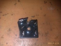
Be carefull when mounting the RIFAs! I have discovered in the bad way that the bottom mounting bolt is electrically tied to the negative side of the cap. I mean the PEH200 series (See picture). The datasheet vaguely point it, but not as clearly as it should be.Right for Rifa caps, I saw their characteristics and they seem pretty good. I think use BHC 10000µF/40V LL caps just after rectifier bridges, then Rifa 47000µF/40V very low esr (0.008ohms 😎)
In the dual PSU amp I am building, everything worked fine outside the enclosure. The first time I powered it on mounted inside the case, it cracked in two the two diode bridges from the negative rail of the supply. I wonder why they tie the mounting bolt to the negative pole, being this a very convenient way to mount the capacitor, and neglecting this advantage as now I have to think how to mount it... electrically isolating this bolt 😱
Attachments
That's how most caps of this type are built, I think.
I had the same issue with my Sikorels. Those diodes sure blow up nice!
I had the same issue with my Sikorels. Those diodes sure blow up nice!
no.The first time I powered it on mounted inside the case, it cracked in two the two diode bridges from the negative rail of the supply.
you cracked the diodes, because you chose to power up direct on line.
Use a bulb tester every time you modify or test a new mains project
- Home
- Amplifiers
- Pass Labs
- F5 power amplifier