Hi All,
I'd like to present You the amp I'm currently using to drive my bass units built with the CIARE HW380 woofer
It almost uses the Douglas Self "Load Invariant" base schema with 6 output pairs of MJL1302A/3281A for each channel, driven by MJE15034/15035.
I put it under a scope and found the following numbers at the first signs of clipping:
160W/8Ohm stereo
510W/8Ohm bridge
800W/4Ohm bridge
The overall protection is built on rail fuses and the delayed relè which is also controlled by an output DC sensing circuit.
A 230V power relè almost immediately shorts a 50Ohm 50W resistor in series with the primary of the 800VA transformer
Attachments
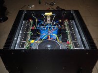
Difficult to tell, but your star ground in the middle of your smoothing caps looks like it is also being used as your Main Audio Ground.
Hi All,
I'd like to present You the amp I'm currently using to drive my bass units built with the CIARE HW380 woofer
It almost uses the Douglas Self "Load Invariant" base schema with 6 output pairs of MJL1302A/3281A for each channel, driven by MJE15034/15035.
I put it under a scope and found the following numbers at the first signs of clipping:
160W/8Ohm stereo
510W/8Ohm bridge
800W/4Ohm bridge
The overall protection is built on rail fuses and the delayed relè which is also controlled by an output DC sensing circuit.
A 230V power relè almost immediately shorts a 50Ohm 50W resistor in series with the primary of the 800VA transformer
you are getting 800watts output from an 800va transformer ...?
you are getting 800watts output from an 800va transformer ...?
Yep. It's positively scary how much one of those things will put out into a short circuit. You can run one about 3x for at least half an hour before anything nasty happens. They don't just 'quit' when you request more than the rating for a fraction of a cycle... unlike switchers which do.
@AndrewT: the Audio Ground is collected on a sort of second start-ground few centimeters away from the main start ground, You can see it between the supply capacitors and the transformers.
Yes, I'm getting 800W @4Ohm bridge and tested with a 100Hz sine wave with a duty cycle of 5s ON and 15 OFF for some minutes after some wrming up at 50W, so It has not been a very hard work for the transformer. Above all I set the limiter on the DCX2496 which is driving it exactly @800W/4Ohm, so I will never exceed the RMS power also when used outdoor; I know this way I'm not getting the maximum peak power but i don't have any method for getting a visible measure of it.
The amp has a total of 166000uF storage capacity (2x39000 + 4x22000) so I'm quite sure it will be able to put out 900W/4Ohm bridge for 50ms peaks
I'm alredy working on a clip indicator based on the Nakamichi PA7 schema, which will be assembled in "free air" and in the future i think i will add a limiter circuit based on the LM13700, like the one I'm working for my new Class G project
do you realise what you have said?Yep. It's positively scary how much one of those things will put out into a short circuit. You can run one about 3x for at least half an hour before anything nasty happens. They don't just 'quit' when you request more than the rating for a fraction of a cycle... unlike switchers which do.
short circuit = zero ohms.
The output power is defined by Po= Imax^2 * Rload.
If Rload is zero ohms then the delivered power Po is zero Watts.
- Status
- Not open for further replies.
- Home
- Amplifiers
- Solid State
- The Amp I use for my bass units