Of course current drive is hardly applicable to speakers which have been designed for voltage drive, i.e. low output resistance.
But it it definetly not a nonsense to build a speaker with current drive in mind, especially for diy or as an active speaker.
But it it definetly not a nonsense to build a speaker with current drive in mind, especially for diy or as an active speaker.
High output impedance of power amplifiers, as seen in many tube amps, IS a bad thing. It will create frequency response with dips and bumps related to speaker impedance curve, and change Q of the bass driver.
Exactly, other than the "bad thing." Whether or not it's a "bad thing" depends on the speaker. See Morgan Jones's "Arpeggio", for example, for how the high source impedance of a SET amp can be exploited to make a flatter overall frequency response. And don't forget the extensive work that Nelson Pass has done with single driver systems and current drive amps.
Hi,
REALLY? I mean it is REALLY "a bad thing"?
I mean, it gives you cancer or something (okay, I'm kidding).
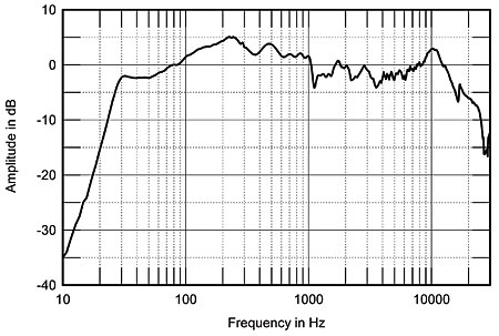
Allow me to take a concrete example. Here is the measured frequency response of a speaker (taken from Stereophile), measured with essentially zero source impedance:
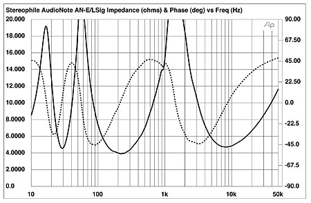
Now let us view the speakers impedance directly below this, shall we?
If we look at the first curve the speaker appears severely non-flat.
Now let's look at the impedance response and estimate what would happen with the kind of source impedance the Cary Amplifier you showed as example of just HOW BAD tube amp's are (say 4 Ohm or a DF of 2)?
First, the peak at 10KHz will be reduced by 1.5dB,.
Second, the region bewteen 600Hz and 4KHz is boosted by as much as 3dB (around 1.5KHz), less towards the limts.
Third, the boosted region around 250Hz will be attenuated by around 3dB.
Fourth, the frequency region around 50Hz is boosted by around 6dB.
In fact, if we where driving this speaker from such a source impedance we would find it to have a reasonably flat frequency response (on axis), contrary to the picture as it appears, because, at least in THIS CASE, the extra source impedance is needed to make the speaker perform correctly. And of course, this speaker was designed to partner Tube Amplifiers with a significnant output impedance.
You are simply wrong.
Ciao T
High output impedance of power amplifiers, as seen in many tube amps, IS a bad thing.
REALLY? I mean it is REALLY "a bad thing"?
I mean, it gives you cancer or something (okay, I'm kidding).
Allow me to take a concrete example. Here is the measured frequency response of a speaker (taken from Stereophile), measured with essentially zero source impedance:
Now let us view the speakers impedance directly below this, shall we?
If we look at the first curve the speaker appears severely non-flat.
Now let's look at the impedance response and estimate what would happen with the kind of source impedance the Cary Amplifier you showed as example of just HOW BAD tube amp's are (say 4 Ohm or a DF of 2)?
First, the peak at 10KHz will be reduced by 1.5dB,.
Second, the region bewteen 600Hz and 4KHz is boosted by as much as 3dB (around 1.5KHz), less towards the limts.
Third, the boosted region around 250Hz will be attenuated by around 3dB.
Fourth, the frequency region around 50Hz is boosted by around 6dB.
In fact, if we where driving this speaker from such a source impedance we would find it to have a reasonably flat frequency response (on axis), contrary to the picture as it appears, because, at least in THIS CASE, the extra source impedance is needed to make the speaker perform correctly. And of course, this speaker was designed to partner Tube Amplifiers with a significnant output impedance.
It will create frequency response with dips and bumps related to speaker impedance curve, and change Q of the bass driver. Sometimes it works like a sort of tone controls. Some may like it, I understand, but it has nothing to do with sound fidelity.
You are simply wrong.
Ciao T
But You should show this image too..
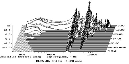
Plain cabinet resonances, nothing else ("audible coloration..")..And coincidence with SPL peaks is obvious..
Plain cabinet resonances, nothing else ("audible coloration..")..And coincidence with SPL peaks is obvious..
Hi,
There are quite broad peaks which the cabinet resonances do not explain or cover.
Ciao T
But You should show this image too..
Plain cabinet resonances, nothing else ("audible coloration..")..And coincidence with SPL peaks is obvious..
There are quite broad peaks which the cabinet resonances do not explain or cover.
Ciao T
I was always speaking about dynamic speakers.
Pavel, your dynamic speakers are kind of artificial. We speak here about experience with real amp+speaker systems. Dynamic speakers are very complex mechanical systems, and electrically can be damped only the main resonant peak on low frequency.
No, say you have an amp with an output coil that drives an ELS. That would also damp the treble.
Pavel, your dynamic speakers are kind of artificial. We speak here about experience with real amp+speaker systems. Dynamic speakers are very complex mechanical systems, and electrically can be damped only the main resonant peak on low frequency.
There is no disagreement. That's what I have shown and I have also shown how the added series resistance increases frequency response resonant bump of a single driver, in case that that single driver was not inherently overdamped. And yes we speak about real speakers which have quite uneven impedance vs. frequency plot with peaks and dips. Again any added series resistance worsens frequency response.
In case that you say that the resistor added in series with speaker does not matter, and that tube amplifier large output impedance does not matter, than we disagree.
This is the impedance plot measured on my real speaker box in real conditions. This is no simulation and no guessing. You guys are going to tell me that placing a resistor in series with it would not matter?? That it would not worsen frequency response?? Are you pushing me to measure a frequency response with added resistor or what???
Attachments

Pavel, I don't discuss speculative matters based on over-simplified models. I speak about real speakers that I have experience with, trying to share (among others who I see have real experience) results of my own work.
This is the impedance plot measured on my real speaker box in real conditions. This is no simulation and no guessing. You guys are going to tell me that placing a resistor in series with it would not matter?? That it would not worsen frequency response?? Are you pushing me to measure a frequency response with added resistor or what???
We are telling you that impedance plot does not have 100% correlation with frequency response, and how close to zero the amp has output resistance does not matter. For some speakers you may need higher resistance, for some speakers even negative one. So called damping factor numbers are meaningless. Stereophile tests of frequency response curve of the amp loaded on simulated some kind of some speaker load is meaningless.
This is not any speculative model, this is a real speaker measured (impedance measurement) in a listening room. Of course that after addition of a resistor in series the frequency response has bumps and dips.
Please show me any mesurement of a complete real speaker that shows that resistor put in series does not affect the frequency response in a bad way. But show me the measurement, there was enough of pub explanations.
Please show me any mesurement of a complete real speaker that shows that resistor put in series does not affect the frequency response in a bad way. But show me the measurement, there was enough of pub explanations.
We are telling you that impedance plot does not have 100% correlation with frequency response,
Only if driven by voltage. In case of a current drive or a resistor in series, the frequency response shape approaches to impedance shape. The drivers are basically designed to be voltage driven, not current driven.
Do You mean, that cabinet resonances should be "cured" by high output impedance? Explaining by Thorsten,that this box is so made intentionally, because it should work correct only with amps with very low DF ,is for me unbelievable..Do you mean cabinet resonances can be damped by low output resistance of an amplifier?
Last edited:
Pavel,
First, few currently made drivers are ruler flat when voltage driven. No matter what, we need to design equalisation for the drivers faults into the system. If we use current drive we need a different EQ (see NP's work).
Second, the voice coil reacts to current, only current and nothing but current. Voltage would not exist safe for the lack of readily available room temperature and above supraconductors.
Third, drivers are basically designed to be intelligently used by intelligent designers.
Intelligent use may include pure current drive, pure voltage drive (pure voltage drive requires negative impedance with Zo = [-Re]+[-all other DCR in the system]) or mixed mode drive with a variety of source impedances (this is the case for almost all Tube and Solid State Amplifiers), given suitable measures are taken to produce a functional design under the required conditions.
The definitions of functional design may vary between different designers, as one may emphases anechoic on axis response flatness over all other considerations, a second one may be aiming at a correct in room transfer function and tolerate greater on-axis deviations and a third may mainly aim at low distortion while accepting larger frequency response deviations both on and off axis and still other designers may emphases correct and constant directivity...
Ciao T
In case of a current drive or a resistor in series, the frequency response shape approaches to impedance shape. The drivers are basically designed to be voltage driven, not current driven.
First, few currently made drivers are ruler flat when voltage driven. No matter what, we need to design equalisation for the drivers faults into the system. If we use current drive we need a different EQ (see NP's work).
Second, the voice coil reacts to current, only current and nothing but current. Voltage would not exist safe for the lack of readily available room temperature and above supraconductors.
Third, drivers are basically designed to be intelligently used by intelligent designers.
Intelligent use may include pure current drive, pure voltage drive (pure voltage drive requires negative impedance with Zo = [-Re]+[-all other DCR in the system]) or mixed mode drive with a variety of source impedances (this is the case for almost all Tube and Solid State Amplifiers), given suitable measures are taken to produce a functional design under the required conditions.
The definitions of functional design may vary between different designers, as one may emphases anechoic on axis response flatness over all other considerations, a second one may be aiming at a correct in room transfer function and tolerate greater on-axis deviations and a third may mainly aim at low distortion while accepting larger frequency response deviations both on and off axis and still other designers may emphases correct and constant directivity...
Ciao T
Only if driven by voltage. In case of a current drive or a resistor in series, the frequency response shape approaches to impedance shape. The drivers are basically designed to be voltage driven, not current driven.
Tell me please how it is designed, and how well it is designed, and what is "it" that is designed. What I see quite often, crossovers are designed such a way they need an amp with zero output impedance and enormous current capability to drive them. And even in such case amps with higher, but more linear, output resistance drive them better than amps with lower output resistance that engage overdrive protection driving such speakers...
The same Stereophile magazine has good reviews of speakers with different plots, both for frequency response and for impedance vs frequency. They are all different, and frequency response is not the only thing that has to be taken care of.
Do You mean, that cabinet resonaces should be "cured" by high output impedance?
Of course not. Quite wild guess... The only resonance that can be "cured" by output resistance is the main resonance of the speaker, but for optimal results as I said output resistance must be optimized for the particular speaker. From higher to negative, depending on the speaker design, and of the system design goal.
Universal amplifiers isolated from speakers is an obsolete concept that only survives in the high end audio niche. Every other application (with the exception of building announcement systems) has evolved to a amp-speaker system approach. Big PA systems do it one way with electronic crossovers or self powered speakers and the $100 iPod dock will have multi-amp with electronic crossovers and dsp correction. In all of those cases the combination of amp and speaker are a system and optimized together. In high end audio they are not. However, that speaker with a significant response variation needs to be matched to an amp that effectively "flattens" it. How much of the magic of these different amp sounds are simply the residue of these interactions?
The old model had the amp as a voltage source and the speaker would give the desired results from a voltage source. Departing from that on either side makes the devices less universal. In effect we are in the same space where a given speaker can only be used optimally with a particular amp and cable combination. Departing from that combination is really tuning to taste (not that the original wasn't mostly tuning to taste) not approaching a basic performance ideal. It also makes any evaluation not particularly useful outside of the specifics of amp-speaker-cable (the cable's effect may be significant) and room.
There is lots of literature on the perception of frequency response errors and the perceived results of small errors. I think that ignoring those identified effects is not constructive.
In a closed system current drive can be perfectly valid since its the combination you are working toward. The relationship between the current to the transducer and the acoustic wave can be remarkable. Otherwise, in an open system, these variations (low damping, higher source impedance etc.) are all unintended tone controls.
- Status
- Not open for further replies.
- Home
- Member Areas
- The Lounge
- John Curl's Blowtorch preamplifier part II