I really can't get my head around this. What is what?
Attachments
Last edited:
 Since this appears to be a guitar amp input stage it should be moved to instrument & amps per forum policy.
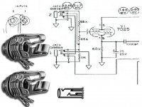
One input is for high output pick ups (the top one) and the other is for low output types I believe. The schematic is not complete so there may be even more going on.
I mean how does it get wired? what is the tip what is the sleeve and so on.
The manufacturer data sheet for the jack should provide that information, worst case you figure it out when you are confronted with the jack as I have had to do. Plugging in a 1/4" phone plug will give you tip and sleeve very quickly, the rest you figure out by inspection and with a meter.
I'm not going to try with those drawings.. 😀
the tip reaches in farthest. It contacts the switch at the farthest end from the facia nut.
The sleeve reaches in the least and contacts the shortest switch.
When looking at the back of the socket you should be able to see the mechanical arrangement and from the 3 solder tags work out which is tip and which is sleeve.
Similarly when looking at the back of the plug, you can identify the Tip, Ring & Sleeve solder tags.
And yes, a resistance meter will show instantly which tag connects to which switch.
Can't get inside the socket !! Insert a plug for unrestricted access.
BTW, a Buzzer on low ohms is very handy for this.
The jacks you are showing are not quite right. The picture shows stereo jacks with a switch on tip and ring. The schematic is showing a mono jack with isolated switch, probably just using the switac to mute the pre-amp out when nothing is plugged in. Those two switches are wired in series from ground and the wire off the lower switch would go to the pre-amp output to mute it.
It looks like the input jacks are wired to accept a normal mono wired guitar through the tube shown, and rout a stereo wired guitar through the tube shown, and through the path not shown. It is not totally clear just what happens with two guitars when one is stereo wired and one isn't.
It has nothing to do with a stereo wired guitar, though a pair of 1/4 males would work in the jacks. It is just two inputs, one being more sensitive than the other.
magicsamin is correct, the pictures of the jacks they used are not the type the schematic calls for. The pictures are for "stereo" jacks, more commonly called TRS (Tip-Ring-Sleeve) jacks. The schematic calls for "mono" jacks with extra cutout contacts. The tip of the plug is the tip, easy enough. And the sleeve refers to the shaft of the plug. In stereo plugs like headphones use, there is an extra band just behind the tip. That is called the ring, hence tip-ring-sleeve. A plain old guitar cord plug - mono - would be called a tip-sleeve.
Ignoring the extra contacts for a moment, this is classic Fender input jack wiring. Each jack shows two sets of contacts. The upper set is the tip contact, which touches the plug tip. There is also a cutout contact bearing on that, so when you plug in, it opens that set of contacts. The lower set on each is what we will ignore for now.
WHen you plug into jack #1, the lower of the two, the contacts on the tip of jack #2 put the two 68k resistors in parallel, so 34k. The 34k is in series with the guitar signal and the grid of the tube, a grid stopper if you will.. However, if you plug into jack #2, then the signal hits the 68k to the grid, but the other 68k winds up from that grid to ground, soo there are two 68k now in series across the signal, with the center point to the grid. This forms a 2/1 voltage divider, cutting the signal voltage in half, a 6db reduction.
SO jack #2 is lower in sensitivity. You usually use jack #1 unless the guitar signal is too hot, then use #2.
Look up the schematic for an old 5E3 Deluxe or maybe a Twin Reverb, and you can see the same wiring without the extra contacts, might be more clear.
And the other extra contacts? The contact in the upper jack is grounded, then the line runs through the second jack and off into the amp somewhere. So that mystery line is grounded until either jack is in use, otherwise it remains grounded. All that is, is a mute. It grounds off the signal path when nothing is plugged in to reduce unwanted noises.
Thank You Enzo. So looking at the schematic from top to bottom you have
Tip
Normally Closed
Ring
Normally Closed
Sleeve
Tip
Normally Closed
Ring
Normally Closed
Sleeve
Not quite. Well depends on which schematic, there is the amp, and then there is the jack alone below.
Remember we said the PICTURES of jacks show TRS jacks with cutouts on both tip and ring. and the little jack schematic next to them shows the correct jack schematic for THEM. But the jacks in the schematic are NOT TRS jacks. They are TS jacks with an extra set of cutouts. The extra set are not touching the plug at all. The pictures are the wrong jacks.
Look at the tip contact. See that double vertical line down to the second moving contact - what you called ring? That represents a plastic lifter. An insulated piece against the tip moving contact, that when the tip is inserted, pushed the lifter, activating the second set of contacts.
See the difference?
I think the jack they used is a Switchraft 13E or equivalent, described as:
"1/4" Mono 2 Conductor Jack w/Nut & Washer, Isolated Break Circuit"
You accurately described the TRS jack shown below the amp schematic, but not the jack in the amp schematic.
I've used the stereo switching type in the pics for a TRS "insert" jack for an effects loop. Similar to an "insert" jack on a mixing board. I've also used mono jacks with multiple switching since they needed replacing in my outboard digital reverb unit.
I don't know why either would be needed for such a 2 input setup as on the schematic. I'm thinking the Fender approach could yield the same results although I'm not sure what the goal is on the scheme. Too much going on for me.
I don't know why either would be needed for such a 2 input setup as on the schematic. I'm thinking the Fender approach could yield the same results although I'm not sure what the goal is on the scheme. Too much going on for me.
I don't know why either would be needed for such a 2 input setup as on the schematic.
also looks to me like the twin inputs are wired in paralel
mono jacks would appear to do the same
Look again. GO through the motions here: Plug into jack #1, note how the two 68k resistors wind up with respect to each other. Now plug into jack #2 and do the same exercise. They are not the same, the jacks are not parallel.
Look at this schematic: http://www.webphix.com/schematic heaven/www.schematicheaven.com/fenderamps/deluxe_6g3_schem.pdf
Same circuit, just without the extra muting contacts. Might make it easier to see what is going on.
The only extra goings on in the OP's schematic is the extra set of contacts on each jack wier in series to ground. And all they do is ground a later point in the signal path if both jacks are empty. Reduces unwanted noise.
This input jack circuit has been used by Fender for well over 60 years, works well, and MANY MANY other brands use the exact same circuit. Again, the purpose of the two jacks is that one of them offers a 6db pad for signals that are too hot. Modern amps now call them "active" and "passive", meaning the hotter active guitar pickups shoul dbe using the padded jack, while regular old passive pickcups would use the unpadded jack.
Here it is again on a current model, this also lacks the extra muting contacts.
http://www.webphix.com/schematic heaven/www.schematicheaven.com/fenderamps/hotrod_deville.pdf
- Status
- Not open for further replies.
- Home
- Live Sound
- Instruments and Amps
- Can someone explain to me this? Please Help