Hi,
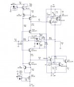
What are you thinking about this circuit of CFP buffer? The different is that I remove resistors on emitter on the driver transistors and they always stay in class A mode. What are you thinking about temperature stabillity, i think to put all transistors on one copper heatsink?
Whether it will works good and stable?
Attachments
Couple of things missing from the schematic...
Missing emitter resistors for the output makes it NOT a CFP...
The DC servo relies on the internal impedance of the source, which may be a problem under realistic conditions.
Why regulate the DC rail that powers a current source since the current source attenuates AC from the rails by several orders of magnitude?
...Missing emitter resistors for the output makes it NOT a CFP...
Yes, that is the idea. What are you thinking about this?
The DC servo relies on the internal impedance of the source, which may be a problem under realistic conditions.
Ok, what is your suggestion?
Why regulate the DC rail that powers a current source since the current source attenuates AC from the rails by several orders of magnitude?
I'm regulating the DC because i want max effectiveness and stability. I'll try to remove a servo.
What are you thinking about termal stability of the circuit? Alll transistors will be on one copper heatsink.
All 4 output devices can be on a single heatsink...........What are you thinking about termal stability of the circuit? Alll transistors will be on one copper heatsink.
The two drivers must be electrically isolated from that same heatsink.
All 4 output devices can be on a single heatsink.
yes,With Q13, 14 temperature tracking can be done.🙂
Hi,
What are you thinking about this circuit of CFP buffer? The different is that I remove resistors on emitter on the driver transistors and they always stay in class A mode. What are you thinking about temperature stabillity, i think to put all transistors on one copper heatsink?
Whether it will works good and stable?
I don't think it will work (well, ok, maybe for a few milliseconds 😉).
There no current limiting in the drivers. The servo only regulates the DC output level, but the drivers can and will conduct large currents meaning the output devices will conduct even larger currents.
You should use emitter resistors in the drivers as a minimum. They can still be in class A, of course.
Another option is to move the emitter resistors from the output devices to the CFP side that connects to the output.
jan didden
Member
Joined 2009
Paid Member
The DC servo relies on the internal impedance of the source, which may be a problem under realistic conditions.
You need to isolate the source from the amplifier by using an input capacitor - this will act as a dc-block and allow the dc-servo free reign that it needs.
- Status
- Not open for further replies.
- Home
- Amplifiers
- Solid State
- CFP Buffer