Nico, you write "this amplifier"...which amplifier circuit do you refer to? The "Randy Sloan" or the "Mitronic" schematic?
The two circuits seems to be different , and which one would you prefer?
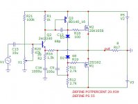
Nico was referring to the Slone (Hitachi) circuit, I think. The Mitronic one is pretty good already. It would probably perform better. The Slone circuit performs well but THD rises rapidly with frequency, or so LTspice tells me. It is simpler to build, but those lateral MOSFETs do not come cheap. Would probably come out costing more, but that's just a guess based on the prices from my local suppliers.
...the mentioned website named the schematic Mitronic .....what's Cresendo?
Got 30 pairs of the Hitachi 2SJ50/2SK135 in 85 . Receipt shows 6£12 each ( close to 9$46) . As I recall ...it was'nt really cheap back then
Lateral mosfet prices have come down by a fair margin, one can now purchase parts with same specs for around 6 pounds a complementary pair. Try the alfet brand, they work fine, that said I believe laterals should always be used with a driver to sound and perform at their best despite many claiming this as a unnecessary evil.
Nico was referring to the Slone (Hitachi) circuit, I think. The Mitronic one is pretty good already. It would probably perform better. The Slone circuit performs well but THD rises rapidly with frequency, or so LTspice tells me. It is simpler to build, but those lateral MOSFETs do not come cheap. Would probably come out costing more, but that's just a guess based on the prices from my local suppliers.
Ok - without that much experience "Mitronic" has a constant generator for input stage and the BF drivers as well as the Hitachi fets "setup" looks like a tubeamp schematic to me.(like that)
To Homemodder.
.....still have the BF's and the Hitachi's in stock....is it better or worse using a double pair of output fet's in your opinion?
Look the Hitachi base circuit is not a bad sounding amp at all and it offers an opportunity with much room for improvement. It can be made very fast and very wide-band. See the thread "the best amplifier I have ever heard". It appeals to me, since most of my amps are based on this foundation with several mods and you can get distortion to disappear into the noise floor if that is the objective.
There are simpler amps that offers even wider bandwidth and faster response to impulse, but a lot of people will shy away from it because it seems too simple to be good. If you are interested I will post it, else build the Randy/Hitachi/Goldmund/Ras/many-other topology, you will not be disappointed with it.
Regards
Nico
There are simpler amps................. If you are interested I will post it
Regards
Nico
why not 🙂
Look the Hitachi base circuit is not a bad sounding amp at all and it offers an opportunity with much room for improvement. It can be made very fast and very wide-band. See the thread "the best amplifier I have ever heard". It appeals to me, since most of my amps are based on this foundation with several mods and you can get distortion to disappear into the noise floor if that is the objective.
There are simpler amps that offers even wider bandwidth and faster response to impulse, but a lot of people will shy away from it because it seems too simple to be good. If you are interested I will post it, else build the Randy/Hitachi/Goldmund/Ras/many-other topology, you will not be disappointed with it.
Regards
Nico
The statement "the best amplifier I have ever heard" is the goal ...and the DIY people here that agrees with me. I like the "valvesound" from fets ... be kind and post your schematic... just to have more circuit choices.
Here we go. There are many varieties you can experiment with. I posted this amp with varients of PNP front end, CCS, etc, each performs a little different. You can add output devices and make a mega amp, the options are open. It works and works extremely well. If I put it in a box and you have no idea of the circuit you would not tell that this is not some very high-end amp.
Attachments

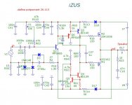
Enough said. Have fun messing with it.
Nico - thank you for the schematic's. ...will try some of your circuits on a woodboard.
rgds.
Gudmund
Hi
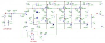
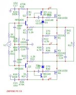
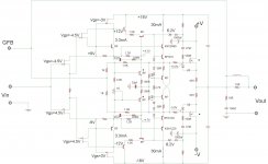
Here is a power follower I made for vertical type Mosfets. Everyone wants to use them 'cause there cheap. The N-ch device I used I paid 67 cents for. P-ch was $1.60 I believe. However most people do not know how to get the best out of this type of device. IMO, source follower is the best way to go because the relativity large gate source capacitance is bootstrapped and has much less effect on the circuit. Essentially you only have to drive the gate-source capacitance with the change in Vgs. To use a higher conductance device with larger Cgs can be misleading in that although the capacitance is larger, the change in Vgs is smaller due to the higher Gm. Cgd is another story but is typically an order or so less in magnitude.
This circuit does not require a higher tier voltage source for the driving stage because the driver supply is bootstrapped. Also the VAS does not have to produce a voltage spread because the input of the circuit works from 0VDC so it can be coupled to any circuit. Since the input Z is very high, the VAS can be a true transconductance amplifier. The +/-9V or so that is needed to bias the HEC and still have enough gate voltage left for Vgsth, comes from the J-fet Vgs bias. The first two do not have to be equal, just so the sum of the two Vgs's adds up to 9V. The unlabeled resistor values would be dependent on what current creates the proper Vgs of the particular J-fet. The bootstrap resistors would be dependent on the supply voltage, +V/-V. J-fets are very fast so do not add much propagation delay in the circuit. Besides, this circuit can be left outside of the GFB loop to act as a pure follower.
Using very high frequency transistors allows for a very large BW for the error amplifier, assuming the RF aspect of the circuit layout is half way sound. No long wires or traces, etc. Since these type of devices are limited in Vceo to 15V or so, cascode is required. The devices with the asterisk are to be mounted together. The small signal devices only need be in thermal contact with the drain pin of the output Mosfet. The compensation of the EC loop is a bit dependent on layout and devices used and would be something to experiment with. In the circuit I put together I used planer stripe mosfets, Q-fet from Fairchild. A pair of TO-220 Q-fets can output about twice the power than is capable from a pair of TO-220 BJT's before they destruct. I find these devices very rugged and fit for duty driving speakers.....that is IF the mass amounts of distortion they create is corrected for.🙄
IF, you don't mind the minor complexity, this is a good solution to the problems of using vertical mosfets as output transistors. The cost of those small signal components add up to still be less than a complementary pair of Laterals....which still have the issue of requiring higher gate voltage drive to fully turn them on. In fact it is much worse because of the lessor Gm of Laterals. In addition they too suffer from the same transconductance droop vertical Mosfets do and this is related to crossover distortion. Anyway, have fun messing with it.😉
Here is a power follower I made for vertical type Mosfets. Everyone wants to use them 'cause there cheap. The N-ch device I used I paid 67 cents for. P-ch was $1.60 I believe. However most people do not know how to get the best out of this type of device. IMO, source follower is the best way to go because the relativity large gate source capacitance is bootstrapped and has much less effect on the circuit. Essentially you only have to drive the gate-source capacitance with the change in Vgs. To use a higher conductance device with larger Cgs can be misleading in that although the capacitance is larger, the change in Vgs is smaller due to the higher Gm. Cgd is another story but is typically an order or so less in magnitude.
This circuit does not require a higher tier voltage source for the driving stage because the driver supply is bootstrapped. Also the VAS does not have to produce a voltage spread because the input of the circuit works from 0VDC so it can be coupled to any circuit. Since the input Z is very high, the VAS can be a true transconductance amplifier.
The +/-9V or so that is needed to bias the HEC and still have enough gate voltage left for Vgsth, comes from the J-fet Vgs bias. The first two do not have to be equal, just so the sum of the two Vgs's adds up to 9V. The unlabeled resistor values would be dependent on what current creates the proper Vgs of the particular J-fet. The bootstrap resistors would be dependent on the supply voltage, +V/-V. J-fets are very fast so do not add much propagation delay in the circuit. Besides, this circuit can be left outside of the GFB loop to act as a pure follower. Using very high frequency transistors allows for a very large BW for the error amplifier, assuming the RF aspect of the circuit layout is half way sound. No long wires or traces, etc. Since these type of devices are limited in Vceo to 15V or so, cascode is required. The devices with the asterisk are to be mounted together. The small signal devices only need be in thermal contact with the drain pin of the output Mosfet. The compensation of the EC loop is a bit dependent on layout and devices used and would be something to experiment with. In the circuit I put together I used planer stripe mosfets, Q-fet from Fairchild. A pair of TO-220 Q-fets can output about twice the power than is capable from a pair of TO-220 BJT's before they destruct. I find these devices very rugged and fit for duty driving speakers.....that is IF the mass amounts of distortion they create is corrected for.🙄
IF, you don't mind the minor complexity, this is a good solution to the problems of using vertical mosfets as output transistors. The cost of those small signal components add up to still be less than a complementary pair of Laterals....which still have the issue of requiring higher gate voltage drive to fully turn them on. In fact it is much worse because of the lessor Gm of Laterals. In addition they too suffer from the same transconductance droop vertical Mosfets do and this is related to crossover distortion. Anyway, have fun messing with it.😉
Attachments
Last edited:
Complimentary pair 2SK1058/2SJ162 from Rensas is about $ 6-00, that is probably as much as a hamburger. So you can build the simple amp for the cost of two hamburgers and a coke.
Ok - without that much experience "Mitronic" has a constant generator for input stage and the BF drivers as well as the Hitachi fets "setup" looks like a tubeamp schematic to me.(like that)
To Homemodder.
.....still have the BF's and the Hitachi's in stock....is it better or worse using a double pair of output fet's in your opinion?
For me its not really a matter of better or worse, depends on the design, for more output pairs you should use higher vas currents, I prefer drivers even with laterals as I can use the vas at lower currents as this usually falls where ft and other parameters of the vas transistor is best, but this also depends on the vas transistor used. Higher speed can also be obtained, have a look at goldmund circuits.
Youre a lucky guy having those hitachis, My fav pair happen to have been 2sj50, 2sk150, I built tons of amps in my teens with these mosfets, the modern pair in TO247 for some reason sound hard and metallic in comparison. I purchased a couple of the to3s from members here to repair some amps I still have from my teens, lets just say I could have bought many hamburgers, and chips and coke.
Last edited:

For me its not really a matter of better or worse, depends on the design, for more output pairs you should use higher vas currents, I prefer drivers even with laterals as I can use the vas at lower currents as this usually falls where ft and other parameters of the vas transistor is best, but this also depends on the vas transistor used. Higher speed can also be obtained, have a look at goldmund circuits.
Youre a lucky guy having those hitachis, My fav pair happen to have been 2sj50, 2sk150, I built tons of amps in my teens with these mosfets, the modern pair in TO247 for some reason sound hard and metallic in comparison. I purchased a couple of the to3s from members here to repair some amps I still have from my teens, lets just say I could have bought many hamburgers, and chips and coke.
The question of one or two old Hitachi output pairs in the one of the mentioned circuits came from a statement in another thread, that we looses details and clear sound by a double pair of powerfets?...not depending upon ft or other specs, but because of the difference inside the N and P type... and as result the matching problem.
And yes...we have tried with a single pair of the TO247 , 2SK1058/2SJ162, based on two different schematics... after test changed to the Hitachi's 50/135 ...and imo the 162/1058 did not reach the Hitachi's...like you we thought ...harder sounding. Unfortunately we lost some of the very clear midrange by use of two pairs...did we do something wrong?
Tinitus, so far that was just put together and simmed, haven't built a balance one just an idea to fiddle with. I have not optimized any components except for the zip file I published, that is an existing working amplifier. I guess one would double up on the FETs for bridged mode since the load halves effectively or run it at a lower voltage, say 30V/30V. My idea is simple to provoke a discussion and get the guys simming and exchanging ideas.
Last edited:
- Status
- Not open for further replies.
- Home
- Amplifiers
- Solid State
- 100watt MOSFET Power Amplifier