Not for very long. The outputs will go into thermal runaway and fail. Those type of fets need to have thermal feedback. If you use Lateral type fets, as the circuit is designed to use, there will be no problem with thermal compensation.
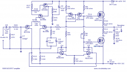
R17 is wrong, 0.6V/47K~13uA. I suspect the IPS tail current is suppose to be a bit more than this.
Those type of fets need to have thermal feedback. If you use Lateral type fets, as the circuit is designed to use, there will be no problem with thermal compensation.R17 is wrong, 0.6V/47K~13uA. I suspect the IPS tail current is suppose to be a bit more than this.
The Hafler DH-200 100 watt per channel DH-200 MOSFET amp works well. You can find the circuit drawing and component listings in the manual link below.
Hafler DH-200 Manual
Hafler DH-200 Manual
R17 should be around 390 ohms then all should work fine. The MOSFETs should be 2SK1058 and 2SJ162
Not for very long. The outputs will go into thermal runaway and fail.
R17 is wrong, 0.6V/47K~13uA. I suspect the IPS tail current is suppose to be a bit more than this.
Swap the pot for a Vbe multiplier and put the transistor on the heatsink.
I have used the irfp240/9240 in dozens of amps.
For better thermal compensation don't use bjt transistor. Use the same type as the outputs like IRF 610/530/540 or other. It tracks temperature much better but if you decide to use bjt will work too.
I suggest that in most cases, use BJT will be better.
They have a minimum VBE. The smallest pay more, and the power of the largest distortion utilization.
And often they better stability.
They have a minimum VBE. The smallest pay more, and the power of the largest distortion utilization.
And often they better stability.
The bias spread between the two gates will be 2 X Vgsth, about 7 to 8V. BJTs have different temperature coefficients than Fets, largly due to the higher transconductance around cut off at the region bias will be set. Using a BJT may overcompensate the Fets, but including an emitter resistor will decrease the gain and temp co. It may require some trial and error to get it just right. IMO, the circuit should slightly overcompensate the output stage bias thermal responce. Since the bias for mosfets should be set above the transconductance droop region, around 150mA, a slight overcompensation should not create problems. Besides, an undercompensated stage is obviously a problem. It becomes a problem to drive the fets all the way to the rail because of the large Vgs required to turn them on. Usually a higher tier rail voltage for the IPS and VAS is required, or a bootstrapped driver stage.
What problem with what current source?
The tail currents in the first and last posts are completely different and result from quite different mechanisms.
What does the capacitance [C7+Cbc] do to the loading on the collector of the LTP?
The tail currents in the first and last posts are completely different and result from quite different mechanisms.
What does the capacitance [C7+Cbc] do to the loading on the collector of the LTP?
Last edited:
PA100 mosfet 1982
Found this 1982 mosfet amp :
https://picasaweb.google.com/103176186685392443797/MitronicPA100#5568058565138346882
Randy Slone might have looked this way, before he designed the amp attached.
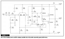
With right sort of MOSFETs you don't need a Vbe multiplier. The design below (by Randy Slone) shows how.
The design looks OK, except for problem with the current source pointed out by Nico.
Found this 1982 mosfet amp :
https://picasaweb.google.com/103176186685392443797/MitronicPA100#5568058565138346882
Randy Slone might have looked this way, before he designed the amp attached.
Ah that sure looks like one of those Elektor lateral MOSFET amps I built a long time ago.
Was it called Crescendo?
Back then, the 2SK135, 2SK50 can be bought for cheap anywhere. Sigh...
Was it called Crescendo?
Back then, the 2SK135, 2SK50 can be bought for cheap anywhere. Sigh...
With right sort of MOSFETs you don't need a Vbe multiplier. The design below (by Randy Slone) shows how.
The design looks OK, except for problem with the current source pointed out by Nico.
The IRF240/9240 in the OP's post definitely need a Vbe multiplier.
With lateral mosfets its a different story.
Cheap Hitachi's...
...the mentioned website named the schematic Mitronic .....what's Cresendo?
Got 30 pairs of the Hitachi 2SJ50/2SK135 in 85 . Receipt shows 6£12 each ( close to 9$46) . As I recall ...it was'nt really cheap back then
Ah that sure looks like one of those Elektor lateral MOSFET amps I built a long time ago.
Was it called Crescendo?
Back then, the 2SK135, 2SK50 can be bought for cheap anywhere. Sigh...
...the mentioned website named the schematic Mitronic .....what's Cresendo?
Got 30 pairs of the Hitachi 2SJ50/2SK135 in 85 . Receipt shows 6£12 each ( close to 9$46) . As I recall ...it was'nt really cheap back then
Double pair of output-fets
Would a double pair of matched power mosfets harm the quality of sound and details from the mentioned schematics by Randy Slone and the PA100 amplifier?
With right sort of MOSFETs you don't need a Vbe multiplier. The design below (by Randy Slone) shows how.
The design looks OK, except for problem with the current source pointed out by Nico.
Would a double pair of matched power mosfets harm the quality of sound and details from the mentioned schematics by Randy Slone and the PA100 amplifier?
This amplifier is not by Steven Jobbs, Bill Gates or Randy Sloan, it is just another interpenetration of the Hitachi application note. There are many versions of it around including my own, Goldmund and several dozen others. It is a great sounding simple amp that has no hang-ups. It works first time and needs no adjustments.
Last edited:
You can add Wilson mirrors, CCS etc it has the potential of many improvements and is a very versatile starting point for a great amplifier.
This amplifier is not by Steven Jobbs, Bill Gates or Randy Sloan, it is just another interpenetration of the Hitachi application note. There are many versions of it around including my own, Goldmund and several dozen others. It is a great sounding simple amp that has no hang-ups. It works first time and needs no adjustments.
Nico, you write "this amplifier"...which amplifier circuit do you refer to? The "Randy Sloan" or the "Mitronic" schematic?
The two circuits seems to be different , and which one would you prefer?
If I may quote myself.
The circuit is from a book by Randy Slone, which is not quite the same thing.
This remark applies to the circuit in post 1, not the Slone circuit.
Aoplogies for any confusion caused.
With right sort of MOSFETs you don't need a Vbe multiplier. The design below (by Randy Slone) shows how.
The circuit is from a book by Randy Slone, which is not quite the same thing.
The design looks OK, except for problem with the current source pointed out by Nico.
This remark applies to the circuit in post 1, not the Slone circuit.
Aoplogies for any confusion caused.
- Status
- Not open for further replies.
- Home
- Amplifiers
- Solid State
- 100watt MOSFET Power Amplifier