A few short cables with crocodile clips on either side is great for exploring groundloop issues.
Member
Joined 2009
Paid Member
Yue1970,
....be careful how you split up this amp into stages for different power supplies. Actually, I don't see how the JLH '69 version can be configured with split supplies, it seems to me it will mess it up.
Another thing - be careful about flux leakage from your power trafo, it can inject hum if you have sensitive circuits nearby.
Voltage regulation will certainly clean up the power rails, but it puts quite a burden on the power supply as you need to allow enough voltage drop across the regulators for fluctuations in the mains AC and this means quite a bit of power dissipation in the regulators. Not that you should avoid this though, it will really clean things up. I don't have enough voltage headroom to do this as my power trafo doesn't give me enough headroom to start with.
Last edited:
Hi all,
Well after a comedy first attempt, I have revisited my 1996 JLH and have finally had success.
I settled for TIP3055s this time as an experiment, and smaller heatsinks than I wanted to use. They get very hot at 1A, so at the moment, I'm not exceeding that.
My PSU is a little underrated in the voltage department. I'm getting +/- 17v from it - so instead of using a 7815 regulator, I'm currrently using a 7812.
oh, and the PSU is unregulated at the moment too - I'm worried that any regulation or capacitance multiplier would drop the voltage too much (how much voltage drop would a capacitance multiplier cause anyway?).
After a bit of tweaking to get the dc offset right (I'm less pedantic about Iq - about an amp will do for now), it seems pretty stable. Even on a rubbish little speaker I had lying around, it sounds remarkable. And very loud.
I've fitted a 1A fuse for now (is that a sensible value?) and I've hooked it up to a Mission 751 and it just sounds awesome! really detailed. I think the lack of class B-esque crossover distortion must make it seem 'louder' than a class B amp (I recall in on of Mr Hood's books, he describes crossover distortion as making the amp sound 'thin').
I have a lot of hum, I suspect that is possibly an earthing issue I have (I haven't exactly followed the earthing suggestions on Geoff's website - yet), but also the PSU is not regulated, and there's probably not enough capacitance (20,000uF per rail at the moment - to be increased).
So, should I consider regulation - even though my rail voltage could drop to something like 14-15V? Or should I go hunting for a different toroid?
20,000 uf for 1 amp current draw is plenty. A little hum (as in ears buried inside bass speaker of a floorstander) would be normal but anything more is not.
So I too suspect your hum is down to wiring issues...
So I too suspect your hum is down to wiring issues...
Ok, well, maybe its an acceptable level of hum then. I first had a lot when I just used the power rail instead of the regulated supply to the dc offset circuit (I didn't think I had enough headroom for a 7815 at 17V). Then I fitted a 7812 for that and it improved, but I was still a bit paranoid about the hum. I can really only hear it with my head next to the speaker.
Been fitting a bracket to a big heatsink in order to fit some MJ15003s to see how that sounds (and so I can set a bigger Iq).
Don't think I'll investigate regulation at the moment, just increase capacitance. I don't want to drop 2v per rail, and I like the idea of low output impedance for the PSU.
Do any of you worry about speaker protection? I have a 1A fast blow fuse at the moment, but am thinking of implementing relay protection (as in Doug Self's book). At the moment, I'm constantly checking the output DC with a multimeter (that's going to be trickier with stereo and one multimeter), and hoping the fuse works (and vowing to not plug in my LS3/5As - no matter how tempting it seems).
Last edited:
As to the hum...
The nature of hum is a big clue. Pure deep 50/60hz is normally induced into the inputs etc. Always evaluate hum with the inputs shorted.
If harmonics are present (harsh raspy sound) then it's actually at twice line frequency and down to PSU/wiring/grounding issues.
Some amps just have a relatively poor PSU ripple rejection ratio meaning noise on one or both rails can be heard.
If the hum varies with bias current (as in more curent drawn = greater ripple) then you have another clue to work on. Try each amp (of a stereo pair if they share the PSU) in isolation, that is to say one amp only powered and its input shorted directly at the input to the amp.
DC offset protection... tough one to answer as it's tears at bedtime if a valued speaker goes up.
If the design is good and properly built and not subject to abuse (shorting speaker leads etc) then I would be reasonably happy without. To me its more important that the design is silent at power on/off with a foolproof arrangement. As to speaker relays, I've been converted to solid state... have a read at this (all of it 🙂)
http://www.diyaudio.com/forums/solid-state/191449-output-relays.html
Thanks for the advice mooly, much appreciated.
I'm happy with the hum level, it is low really (I'm used to class B amps with virtually no hum at all), but I will investigate. I hadn't thought of lowering the bias (although I was keenly aware that I'd get more ripple when I up Iq).
Now running with MJ15003s on a bigger heatsink. Takes longer to heat up, but still gets rather hot 🙂. Can't really tell if it's better (possibly is) than TIP3055, as I'm listening in mono, but I can play with increasing Iq.
After an initial settling time of a couple of minutes, and setting the DC offset to close to zero, the DC offset rose by only about 2 hundredths of a volt - so does seem quite stable (I wonder if it will ever completely settle? I guess so).
Thanks for the link, I shall have a read...
That's a very low DC offset for a single ended DC coupled amp (I remember JLH presenting the modified version in Wireless World). It will never be totally drift free or absolutely stable with temperature but it's good enough.
From memory... in the Wireless World article there was an error. The feedback return electroylitic was shown coupled to the negative rail ? rather than ground and that worsened the hum/noise performance. A correction was issued. Wiring is so important... even a cm or so of wire or print develops enough volt drop (depending whats running through it) to cause hum if say a feedback return and input ground share that connection.
From memory... in the Wireless World article there was an error. The feedback return electroylitic was shown coupled to the negative rail ? rather than ground and that worsened the hum/noise performance. A correction was issued. Wiring is so important... even a cm or so of wire or print develops enough volt drop (depending whats running through it) to cause hum if say a feedback return and input ground share that connection.
It might be a low offset, but I deliberately tweaked it to that (it may well be different next time). I am only drawing an amp at the moment - so that might be helping to keep it stable.
Yes, I did spot the error in the schematic when reading the article.
I'm very certain my wiring can be improved. It's just on a bench at the moment. I built the circuit boards out of veroboard about 4 years ago. They contain pretty much all but the output transistors and 0r33 resistor (which are connected together at the moment with choc-block, but will eventually be p2p soldered, with shorter length wiring).
I'll try and upload some photos at some point.
Ken, I'm not sure what you're trying to achieve with your suggestion, DC blocking?
Yeah, intended for DC blocking the feedback path.
Keeping cap(s) biased, but not injecting ripple or thump.
Keeping cap(s) biased, but not injecting ripple or thump.
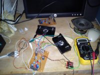
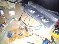
Thought I'd get some photos to you...
Basically two photos. The first is the first lash up using TIP3055s. They were on small black heatsinks, so they were super hot even at 1A. Then I migrated to MJ15003s, as in the next picture - with a non ideal construction of aluminium sheet bolted to large heatsink (with heatsink compound between the two). Even though this has two devices, it takes a while to get toasty at 1A, so working well enough (even if not strictly perfect).
This evening, it drifted a bit more than last time (still only 2-3 hundredths in half an hour - after the first few minutes of settling). Perhaps there was error in my measurement, but rather stable it seems.
Haven't increased Iq yet, don't see the need yet (I haven't had the chance to play this loud yet - it's in the garage, I'd annoy the neighbours).
Thanks to all for the help, Obviously Mooly and Ken, but also Geoff, and other contributors to this thread (I have been reading it over the years 😉 ).
Now to get the second channel working, play with wiring, try a constant current source, build a chassis, read that relays thread, convince my wife it should be allowed indoors... The list goes one. Who knows when I might get back to playing with my DAC! 🙂
Attachments
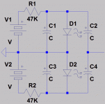
Feel bold enough to become Guinea pig for a shunt regulated bootstrap?
Between your outputs, series a pair of 0.33R for purpose of sensing current.
Loudspeaker load to be connected between resistors, if not self-evident.
Use the voltage drop across these resistors to drive 2n2222 base to emitter.
Tie the collector of this 2n2222 to the base of your upper output transistor,
to steal current from the bootstrap whenever Class A output exceeds 1A.
OK to run your bootstrap a few mA hotter than normal for your 1A output.
Just enough so the 2n2222 always has something extra to shunt, and never
tempted to accidentally turn off.
If you can bond shunt transistor to your heatsink, it will also fight runaway.
Only 1.4V at shunt collector, not likely to become hot of it's own workload.
If it feels heat, current sensed across base to emitter junction goes down.
Last edited:
Yes, I do want to make a chassis. Been thinking if I can conveniently mount the circuit board to the heatsink somehow (and still have access to the trimpots). First of all I want to get the second channel working.
Ken, I want to get it working as is first, not sure I could change the circuit board for bootstrap with much ease, I did deliberately leave the regulator for the DC offset on a seperate board - so I could replace that with a CCS (alas, not so simple to place a CCS for Iq setting, but maybe doable if needs be). Anyway, I want to get it all working first before I start meddling.
Ken, I want to get it working as is first, not sure I could change the circuit board for bootstrap with much ease, I did deliberately leave the regulator for the DC offset on a seperate board - so I could replace that with a CCS (alas, not so simple to place a CCS for Iq setting, but maybe doable if needs be). Anyway, I want to get it all working first before I start meddling.
Oh, you mean offset CCS? I thought you meant drive CCS.
Was only talking drive, never gave a moments thought to
offset correction as something you would fix with a CCS.
I thought 69 JLH had an unregulated bootstrap for drive?
If you have no CCS and no Bootstrap on your circuit board,
what exactly did you use for that function instead?
My proposed solution can be entirely off-board and requires
no extra wires back to the PCB. You want the bias thieving
transistor and current sensing resistors all together on the
output heatsink assembly anyway. Just three components...
Last edited:
I've built the 1996 JLH, not 1969. So, I have dual power rails and no output capacitor (hence my concerns about DC offset drifitng and speaker protection). It doesn't have a bootstrap. It has two trims for Iq and DC offset respectively.
On Geoff's website, the update suggests the use of adjustable CCS for these two functions. The 1996 uses a 7815 (or 12v version in my case) as a smoother than the rails DC to originate the DC offset from to add to the feedback path. Regulators aren't great over a large bandwidth, hence the move to a CCS for this. I think.
http://www.tcaas.btinternet.co.uk/jlh1996.pdf
The Class-A Amplifier Site - JLH Class-A Update
You don't need any bootstrap, I just assumed you had built the simplest way
with minimalist component count.
Don't need a fancy CCS. But if you already have one, it won't hurt anything.
The main purpose of shunting is to shape a linear result that can't runaway.
But if you had the older JLH with an unregulated bootstrap, the shunt would
also serve to clean that into an ideal current source.
Note the ideal current sourrce for JLH is not a constant drive current, but
one that produces linear vs linear output currents with a constant sum.
See the three new parts on the right R1 R2 Q3.
Can all be located on heatsink, no board mods or extra wires.
Drive current source I1 does not need to be anything fancy.
The shunt will remove any excess beyond what makes a pair
of linear outputs centered upon 1A quiescent.
Can all be located on heatsink, no board mods or extra wires.
Drive current source I1 does not need to be anything fancy.
The shunt will remove any excess beyond what makes a pair
of linear outputs centered upon 1A quiescent.
Attachments

- Home
- Amplifiers
- Solid State
- JLH 10 Watt class A amplifier