Puffin,
good advice, make the learning curve as slow as the learner needs. Start simply and build up from that knowledge.
I really like the schematic you have shown. It clearly shows the separation between the Signal Ground and the Power Ground. Pity the decoupling is not shown as it should be assembled.
But Worse.
The Disconnecting Network between the Power Ground and the Chassis cannot pass "Fault" current to Protective Earth (PE). This Network must include a component that can pass kA in either direction until the mains fuse ruptures.
yes quite steep haha. I did not think to power it up with the light bulb in place as it has all worked before and i hand't changed anything electrically. This time it worked until i put the signal in.
Can the light bulb test be used in anyother way beside a saftey to check power up? when you go to run the amp properly do you have to take the light bulb out?
Dion
ps. got a single lm3886 chip coming so i guess i'll build a point to point one before replacing the one on the board with it.
[edit] yea normally i put a 35A rectifier (both ac connected to ground, both dc to voltage) in the disconecting network to pass that fault current.
Last edited:
Again in my case, the bulb tester simplified the debug process by allowing me to work with each segment (LM3886 leg) separately. If one replaces a component in that segment one at a time, the guesswork is greatly reduced compared to replacing multiple pieces of the same component. It's a "check as you go" process.
bcmbob, so you saftey a part of the circuit with the light bulb and replace each component one at a time to find you problem right?
also not sure about, can you play music and hooked up to a speaker with the bulb in?
Dion
also mine is a parallel /btl with 4 chips, so not sure what i would do there haha
also not sure about, can you play music and hooked up to a speaker with the bulb in?
Dion
also mine is a parallel /btl with 4 chips, so not sure what i would do there haha
The bulb allows the modified equipment to power up without destroying itself.
When powered up, even with the bulb glowing, one can take voltage measurements to try to identify why the bulb is glowing.
Yes, a ClassAB amplifier can run on a bulb ballasted PSU. But don't expect to sound great. The PSU voltage modulation (due to the bulb) may be getting past the amp PSRR and into the speakers.
On this design removing the vertically mounted black resistors decouples the entire LM3886 leg. Yours appear to be the white cement type. Reinstalling the resistors one at a time allows investigation of each segment. If all is as it should be, the bulb will fade to off indicating correct flow of the current.

Individual segments clearly seen on bare PCB

I also built this rig to dissipate the charge in the power supply caps as I worked. The caps can hold a charge for a very long time

Individual segments clearly seen on bare PCB
I also built this rig to dissipate the charge in the power supply caps as I worked. The caps can hold a charge for a very long time
Last edited:
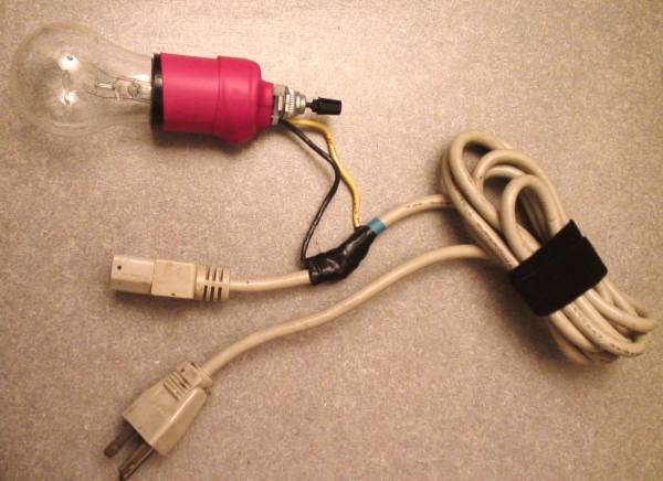
Here is a straight forward simple bulb tester. Just inserted in black wire. The switch is there only because that's the socket I had on hand at the time - always in on position.

Last edited:
Puffin,
good advice, make the learning curve as slow as the learner needs. Start simply and build up from that knowledge.
I really like the schematic you have shown. It clearly shows the separation between the Signal Ground and the Power Ground. Pity the decoupling is not shown as it should be assembled.
But Worse.
The Disconnecting Network between the Power Ground and the Chassis cannot pass "Fault" current to Protective Earth (PE). This Network must include a component that can pass kA in either direction until the mains fuse ruptures.
Andrew. I have been looking at the ESP site, is this what you were referring to?
The resistor R1 (a 5W wirewound resistor is suggested) isolates the low-voltage high-current ground loop circuit, and the diodes D1 & D2 provide a protective circuit in the event of a major problem. These diodes need only be low voltage, but a current rating of 5A or greater is required. The 100nF capacitor (C1) acts as a short circuit to radio frequency signals, effectively grounding them. This should be a device with very good high frequency response, and a 'monolithic' ceramic is recommended.

Rob.
Last edited:
Puffin, yes i believe that is what he was referring to (D1 and D2).
AndrewT, thank you 🙂
bcmbob, also thank you very much.
i'll be sure to use that from now on
Dion
AndrewT, thank you 🙂
bcmbob, also thank you very much.
i'll be sure to use that from now on
Dion
post28
yes,
that is a usable Disconnecting Network (DN)
You can replace the resistor with a thermistor if you think it will help. It does no harm to replace the 5W resistor with a 1/4 (250mW) resistor
You can add a futher parallel component to aid operating flexibilty. Add a switch or shorting link.
With the switch closed, the Main Audio Ground (MAG) is directly connected to Protective Earth (PE).
With the switch open the MAG is not directly connected to PE, there is the DN in between.
The Chassis is always connected to PE irrespective of what position the switch(shorting link) is in.
post28
yes,
that is a usable Disconnecting Network (DN)
You can replace the resistor with a thermistor if you think it will help. It does no harm to replace the 5W resistor with a 1/4 (250mW) resistor
You can add a futher parallel component to aid operating flexibilty. Add a switch or shorting link.
With the switch closed, the Main Audio Ground (MAG) is directly connected to Protective Earth (PE).
With the switch open the MAG is not directly connected to PE, there is the DN in between.
The Chassis is always connected to PE irrespective of what position the switch(shorting link) is in.
Good suggestion. I have some CL60s I could use in place of the resistor.
So i was thinking about my amp again today and i was looking for a more unconventional reason for its failure. please note that pin 4 (V-) is almost touching pin 3 (OUTPUT) so im assuming that's where the shorting occurred.
The reason im looking for something different is that everything has run before in exactly the same setup; including that day. As i connected the audio i trimmed some RCA wire to plug into the amp. the reason i mention this is that wire was made up of about 5 quite thick strands of copper. I may be insane and just looking for other possibilities but a bit (which would have been of perfect size) of copper could have landed on the wires on an lm3886? unlikely i know, just looking for explanations for it to go wrong at that stage. also while powered (during and after short) the sub gave a decently strong constant output around the (what i would guess to be) 120 hz range.
how insane am I? im tired so im assuming quite haha
Dion
- Status
- Not open for further replies.
- Home
- Amplifiers
- Chip Amps
- LM3886 amp board sparks and smoke