Yes, I know there is a thread giong on F5X EUVL Approach but the diy Store boards are available and why not use them?
I'm currently building 2 mono F5X with the P-F5c-2V20efrom the diyAudio Store.
those are the boards with cacode option and 2nd output pair option.
I'll build the 2nd output option and "X" 2 boards for a mono block.
AFAIK Smyslow did this with the 1 output pair boards but it was not further commented.
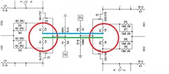
To "X" the boards two pcb connections need to be cutted. Not nice but the boards have no "X-Option". See picture.
Here are my first 2 questions to the knowledgeable:
1. Input impedance
If I go with the 1k input resistir plus 100k reference to ground as in the original F5 I'll end up with only 500 ohms input impedance in a X design. This is fairly low. I built my AX amps with 10k input impedance and 10k reference to ground.
Here I would like to go with 22.1k input impedance and 221.1k reference to ground.
Would this be ok?
2. Relative DC offset resistors output to ground
Would it be helpful to implement the output to ground resistors from other X designs (33 to 68 ohms plus/minus output to ground) also in this design? Or is it unneccessary? If yes, why?
I'm currently building 2 mono F5X with the P-F5c-2V20efrom the diyAudio Store.
those are the boards with cacode option and 2nd output pair option.
I'll build the 2nd output option and "X" 2 boards for a mono block.
AFAIK Smyslow did this with the 1 output pair boards but it was not further commented.
To "X" the boards two pcb connections need to be cutted. Not nice but the boards have no "X-Option". See picture.
Here are my first 2 questions to the knowledgeable:
1. Input impedance
If I go with the 1k input resistir plus 100k reference to ground as in the original F5 I'll end up with only 500 ohms input impedance in a X design. This is fairly low. I built my AX amps with 10k input impedance and 10k reference to ground.
Here I would like to go with 22.1k input impedance and 221.1k reference to ground.
Would this be ok?
2. Relative DC offset resistors output to ground
Would it be helpful to implement the output to ground resistors from other X designs (33 to 68 ohms plus/minus output to ground) also in this design? Or is it unneccessary? If yes, why?
Attachments
Last edited:
Input impedance F5X
Is there really nobody who can help me with input impedance of X-Amps and relative DC offset resistors?
Is there really nobody who can help me with input impedance of X-Amps and relative DC offset resistors?
just use EUVL's schmtc
Exactly this information was left out by EVUL
you need to cross these two green/blue lines ;
in this moment my brain is sort in red , so check that twice
gimme entire schematic which you want to use , so I can comment
in this moment my brain is sort in red , so check that twice
gimme entire schematic which you want to use , so I can comment
OK
use 1K in series with gates ( anti-oscillation measure ) , then anything between 22K-47K from gates to gnd .
that will be input impedance for each leg .
NB that's not same as XA amps , where is used inverting stage NFB for establishing SUSY function , which means that series gate resistor is dictating input impedance .
OK
use 1K in series with gates ( anti-oscillation measure ) , then anything between 22K-47K from gates to gnd .
that will be input impedance for each leg .
NB that's not same as XA amps , where is used inverting stage NFB for establishing SUSY function , which means that series gate resistor is dictating input impedance .
Thank you!
THAT was helpful
Output resistors?
you need to cross these two green/blue lines
Look at the inverted left part of the schematic.
They are already crossed
EUVL's schematic can be found in post #1216 of the F5 thread.
1 "Kiste" Beer if you show me the input resistors in that schematic
Look at the inverted left part of the schematic.
They are already crossed
you got me there 😉
1 "Kiste" Beer if you show me the input resistors in that schematic
naah .... there aren't any ;
but you know that you must have them
what with them ?
Output to ground resistors 33 to 68 ohms to stabilize relative dc offset.
Are they helpful in this design?
> you already have them - look at feedback net
But not when you float the X, dear Choky.
I personally would put 220R 1W to Gnd at both outputs.
But feel free to experiment.
No need to challenge Heinz1 for eine Kiste Bier.
I did not put the input resistors on the schematics, not even on the main PCB.
They are the same as in Nelson's single ended F5.
So I only posted the parts that needed to be changed.
Thought it was trivial.
Patrick
.
Last edited:
Oh, BTW, there is at least one very good reason why the proper F5X board is superior than 2x single ended F5 board for this build.
I let you think about it first.
It has to do with the power supply.
Patrick
I let you think about it first.
It has to do with the power supply.
Patrick
I personally would put 220R 1W to Gnd at both outputs.
But feel free to experiment.
Thank you!
So I only posted the parts that needed to be changed.
Thought it was trivial.
No!
Clipping Q1/Q2 ??
Is it possible to drive Q1/Q2 into clipping?
When testing the Boards with 2 output pairs into 4 ohms (not yet x-ed) I get clipping at 2.2 to 2.3V input. With this input I get around 50W into 4 ohms. No improvement over the version with 1 output pair.
This clipping appears independent of the values of the current limit circuit. I can even leave the circuit out.
It is a voltage clip.
The circuit has a gain of 6. So output is at 13.8V with 16V rails.
As expected not enough headroom left for the MOSFETs.
Since you are using 2 output pairs, you can increase rail voltage and reduce bias current per FET while keeping dissipation per FET below 32W.
I would try 20V 1.6A per FET as a start.
Patrick
1 "Kiste" Beer if you show me the input resistors in that schematic
This is how I built one:
http://www.diyaudio.com/forums/pass...world-class-cascoded-balanced-xf5-budget.html
I used 1K and 100K as NP did in the original and have no problems.
- Status
- Not open for further replies.
- Home
- Amplifiers
- Pass Labs
- F5X from diyAudio Boards P-F5c-2V20e