Hi all,
I've been looking into a series of OTL designs, but none really made me happy, namely because they lack symmetry and hence require "adjustments" which I do not trust to be stable over time.
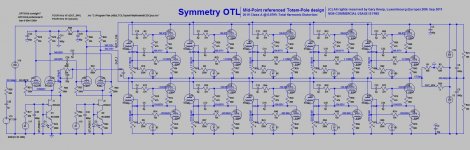
My goal was to design an OTL which is symmetrical in nearly all regards.
Efficiency, costs, heat dissipation were no issue, only the (yet theoretical) quality of the amplified signal was my goal.
The mid-point referenced totem-pole allows such a design.
For each output tube, I've added its own driver stage with local feedback. The overall feedback loop allows more power but will (moderately) increase THD values, now very low at 0.079% at 20 W.
Now this is a LTspice simulation only, so please go ahead and give me feedback on this.
Please send me an email for getting the design and its library : email address removed Please PM
Thanks, Gary
I've been looking into a series of OTL designs, but none really made me happy, namely because they lack symmetry and hence require "adjustments" which I do not trust to be stable over time.
My goal was to design an OTL which is symmetrical in nearly all regards.
Efficiency, costs, heat dissipation were no issue, only the (yet theoretical) quality of the amplified signal was my goal.
The mid-point referenced totem-pole allows such a design.
For each output tube, I've added its own driver stage with local feedback. The overall feedback loop allows more power but will (moderately) increase THD values, now very low at 0.079% at 20 W.
Now this is a LTspice simulation only, so please go ahead and give me feedback on this.
Please send me an email for getting the design and its library :
email address removed Please PM Thanks, Gary
Last edited by a moderator:
I posted an OTL design a little while back based on the Inv. Futterman, Be interesting to see yours for comparison....
I posted an OTL design a little while back based on the Inv. Futterman, Be interesting to see yours for comparison....
Hi dear, I'm pretty new using this Blog, so I've some issues to upload my project files. I hope that a JPG comes thru...
Gary
Attachments
Ho-Hum!
Are you Serious!
ALL those 6C33C, and ONLY 20W! 10 6C33 Per Channel--Guess you have a HUGE Air-Con in your house!
--With THAT many, you should be running a couple of Hundred Watts O/P power!
In Circlotron, Ive got 56W RMS from just a Pair at 200V per rail!
Are you Serious!
ALL those 6C33C, and ONLY 20W! 10 6C33 Per Channel--Guess you have a HUGE Air-Con in your house!
--With THAT many, you should be running a couple of Hundred Watts O/P power!
In Circlotron, Ive got 56W RMS from just a Pair at 200V per rail!
Hi, 10 pairs of 6C33 are OK for getting a low Outpiut impedance, I didn't want using a Futterman design as it is - to my appraisal - not symmetric, and this was a design goal.
Power was NO design goal, Low THD was.
Gary
Power was NO design goal, Low THD was.
Gary
Well Totem-Pole aint really symetrical either IMO!
--Thats why Futterman put the phase-splitter riding on the O/P to compensate for the drive requirements of the two sets of O/P tubes....
A Circlotron could be done that suits your requirements, 'symetrical' Much easier, and with much less tubes, and a great performance too!
A little neg feedback will lower the O/P impedance so you dont NEED Loads of mega hot tubes!
Have you a three-phase supply in your house? Guess the power cons. of your design will be horrendous!
As a matter of interest, Have you made amps using the 6C33C tube, They Get Amazingly HOT...?
Hi, symmetrical as I use it semantically means that I use two floating Power Supplies and that the upper side of the amp is strictly identical to the lower part, actually it's a cut and paste operation. The Futterman solution is not symmetrical in that sense.
Now the design's goal was not efficiency, there I do fully agree that a Circlotron will likely be more reasonable. In this sense, I could have taken out the Cathode Follower stage for each 6C33 tube and leave everything to the overall feedback loop.
My goal is very low distortion levels at nominal power, 20 W are largely enough. I can likely take out 2 pairs of 6C33, lower a bit the feedback controls and still get 20 W out at a slightly higher THD level, but I have not yet estimated the impact on the damping factor.
Rgds/Gary
"Futterman design as it is - to my appraisal - not symmetric"
But the Futterman is symmetric, i.e it is fully balanced and gives very low 2nd order distortion, I get about -55dB, (measured) 2nd order with no global feedback. The uncompensated totempole is as Alastair write not at all balanced and gives hugh amount of 2nd order. What model did you use for 6C33C? most available models are just awful and are not even close to the real thing, the model presented here is the best I have found but it doesn't give correct distortion either.
BR Hans
Hmm--Lets look at power/heat etc for a minute.....
280mA through each 6C33C (1.1 odd volts across each 4 ohm cathode-resistor)
225V per rail.
Each tube will be dissipating 225 x 0.280, = 63W or therabouts
(BTW, Running a 6C33C at Just Over MAX PLATE diss which is 60W is asking for trouble!--Should keep it well below that. Recommended is below 40W P diss.)
This times number of tubes, (10) is 630W just in plate diss. for a Single-Channel.....
Add then the 30 ish watts Heaters for each one, so 300W ish....
We are up to nearly a Kilowatt of Power Cons, plus the drivers and pre-amp tubes, to make just 20W of sound output power....
And, You are gonna build a PAIR for stereo! Eee gads, Thank all thats Holy I aint paying your elect bill!
TBH, Its a non-starter in my book, Others may think otherwise, but its not for me personally!
I should look a bit closer before saying anything, but why AC-coupled NFB? Don't u want the NFB to help keep down the offset? Also why hook up the lower (CCS) part of the driver with the cathode resistor of the output tube? I know it's a way to limit output current and common with SS, but no need here, besides, wont that kill all the dynamics and severely restrict max power? Why so mane output tubes in parallel? Only to lower Zout, or does it help lower thd in the sim as well? (I doubt it sounds any better than a single pair).
Anyways, nice to see someone not afraid of going 'more-is-more', since I'm more of a 'less-is-better' type and can go it a bit too far sometimes. But really tho, this design would be a nightmare to build, and the power consumption, man what are you thinking? Are you a pro-nuke-power dude?
Another thing, being a totempole design. How can this show such low thd when the two phases are driven non-compensated for the different gain in the upper and lower pair of output devices?
Last edited:
GKN202....
I would recommend you read Hans site (TubeTVR) He has done a very excellent write-up on the 'totem-pole' types and their variations like the Futterman and its variants, with the pro's and cons for each design.
He also has an excellent design based on the Futterman, and if truth be told, my 'small' OTL is based rather roughly on it....
Hi, let's take softly. Forget the input stage, and just look at ONE piece of an upper and lower 6C33 tube set, there are 5 thereof.
My design goal was to build a power stage that is controlled by a CF with local FB and to have a cut & paste approach. The Bias is controlled by an autobias circuit and will not be implemented as given in the published model. I fully agree on the bias setting being too high.
Power consumption is not a design goal, my goal is to bring the distortion below 0.1% with a low level of FB.
Gary
But, How are you compensating for the difference in drive requirements for the upper to lower tubes?
The gain for each is different, and therefore must be accounted for or extreme 2nd harmonic dist will result....
--Regardless of what the simulation says!
(Pointless simulating Tube circuits IMHO, It Never turns out like that in real life....)
Also, You mention 'Floating Supplies' for your O/P stage....
then why are they 'commoned' at the '0'V Gnd point??
Last edited:
After looking at the schematic carefully, it does appear to be balanced as stated. It IS a Circlotron design, but with one of the power supply/tube strings reversed in order. This just puts a DC offset to that side, but AC wise is still balanced.
You can look at the circuit as two big cathode followers, each driving half the load with respect to ground. It's just that one has a floating supply in the cathode side instead of the usual plate side. Performance should be identical with the Circlotron.
Have to agree with the power consumption comments though. I also would point out that a cathode follower works better the higher the gm. So just put two Mosfets in (instead) and it will work better, more linearly, lower Zout, and more efficiently. Low turns ratio transformers also work excellently, so could just use one with a single pair of 6C33 to get very low Zout and low distortion. OTL, YUK!
It seems like an outright Circlotron would be easier to draw.
The Circlotron was mentioned several times in this thread but those comments seemed to be ignored by the OP.
I'm pretty sure I can get 20W from just a pair of 6C33s. Its no problem getting 30 watts from 5 6AS7Gs.... that's 12.5 amps of filament current as opposed to about 16 amps.
The Circlotron was mentioned several times in this thread but those comments seemed to be ignored by the OP.
I'm pretty sure I can get 20W from just a pair of 6C33s. Its no problem getting 30 watts from 5 6AS7Gs.... that's 12.5 amps of filament current as opposed to about 16 amps.
This guy in Bulgaria has designed an OTL 6C33. I don't know a thing about it, I just bought some tubes from him and he told me he had one. I think he does have kits, or at least he had one I was looking at. Nice man. Here is the web site
Hartung OTL
Thatch
Hartung OTL
Thatch
THD values, now very low at 0.079% at 20 W.
Don't believe it.....Let's see the basic test specs that lay claim...?
It seems like an outright Circlotron would be easier to draw.
The Circlotron was mentioned several times in this thread but those comments seemed to be ignored by the OP.
I'm pretty sure I can get 20W from just a pair of 6C33s. Its no problem getting 30 watts from 5 6AS7Gs.... that's 12.5 amps of filament current as opposed to about 16 amps.
I'm sure it would be difficult to get Less than 20W outta a pair of 33C in Circlotron if done properly!
Ive had a pair give 56W RMS in Circlotron just before clip, so I guess this tends to suggest that hurds of tubes aint needed for a moderate power output and good quality sound....😀
A conventional Circlotron circuit could eliminate the need for caps in the drive section coupling and optionally in the feedback path, since the large DC offset on the bottom side of the Totem Pole setup would be removed. What the OP found thru simulation though is quite expected. OTL grossly overloads the output tubes, causing severe distortion, unless either a lot of tubes are paralled or huge amounts of NFdbk are applied. Same issue with Zout. Putting in a low ratio OT would help immensely, and save KiloWatts too.
- Status
- Not open for further replies.
- Home
- Amplifiers
- Tubes / Valves
- Totem-Pole OTL with 6c33c tubes and 0.079 % THD at 20 Watt