Hi,
Yes.. Thank you for good word... 🙂
Sorry for mess, but I have sen you a link to the wrong measurements... To many projects are going on in parallel. Here are correct measurements:
Yes.. Thank you for good word... 🙂
Sorry for mess, but I have sen you a link to the wrong measurements... To many projects are going on in parallel. Here are correct measurements:
Attachments
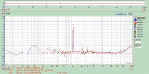
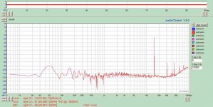

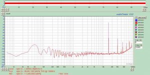
Little bit more tuning of DC transistors' working points and even better results:
Mach Audio - Profesjonalny Sprz?t Audio
The last plot is power bandwidth
Mach Audio - Profesjonalny Sprz?t Audio
The last plot is power bandwidth
If you probe the VAS current you'll find that the BJT CCS draws the majority of it, with the MOSFET gates consuming only a miniscule fraction. The bootstrapped Jfet we use will help with this greatly.
- keantoken
- keantoken
Last time I communicated with Hugh we was playing about with different compensation methods - I wonder if he came to the same conclusion as me
I had been aware that my amp probably needed a bit more compensation so I went to 15pF + 100R of lead compensation. It did smooth things out a bit but the sounds was truly depressing compared to the previous 8pF of lead + 2pF of lag
Today I switched to 17pF of lag ( miller ) compensation and it's hard to explain to you how much the sound improved - so much smoother and clearer but also still with excitement & very relaxed sounding.
So Hats off to you Hugh - you said I would need some millar compensation to make the amp sound good and you were absolutely right.
Greg also mentioned to me that he preferred miller compensation compared to lead compensation - so it looks like we may be unanimous on this topic
I will experiment with other values but even now the sound is quite sublime.
Just to remind you: my gain is 11 and I am DC linked throughout and my VAC device is ZVP3310a
Last edited:
Mine sounds the best so far with about 56pF miller compensation, no phase lead. I have not yet been compelled to make any further tests. 🙂
- keantoken
- keantoken
Mike, Kean,
Your LC figures are different of course because I believe Mike uses the new pcb, while Kean is using a proto layout? Is this correct?
I have NOT used a phase lead cap, only 33pF lag comp, and report good results, but have not taken it further. Today I'm putting the amp into its box, so will take the chance to fiddle a bit with LC. I fully expect that less will be more, in fact. This aspect of amp design bugs me because it's so empirical and the effect so sonically pronounced, but clearly it is vitally necessary.
It's a damn good sounding amp, however, I'm very pleased with it.
Cheers,
Hugh
Yes, I'm still using my first layout. I also use active rail filtering, with my K-multipler design. I'm sure that has some effect. I also use a different VAS, and a different input FET!
I had an idea concerning the rail filtering. AKSA and others preferred an RC filter. AKSA eventually settled on 10R for the R, to lower the amount of filtering. I wonder if a better solution is to put an R in series with the cap, as this will preserve the bass response of the filter, while still decreasing the filtering effect. This may require an extra film decoupling cap, to preserve HF filtering.
- keantoken
Compensation
I have said on several occasions that miller comp with this amp does not sound too bad at all, and that I prefer it over phase lead for this amplifier. In fact my final schematic shows miller comp only, a value of 33pf.
I think miller comp works well with this amp because the fets already have so much of it inherently. Adding more simply stabilizes and linearises the miller effect.
The relatively low OLG of the circuit means we can't afford to lose any by using phase lead compensation. The life simply disappears. This is my impression at least.
Now, can I try and suggest something else a little against the norm? Try removing your miller cap altogether, or dropping it to a very small value. Then add a HUGE output choke to your amp. I am talking perhaps a metre of wire or more in the coil.
I think you will be very very pleasantly surprised at how nicely this pulls the treble into line. A slightly harsh treble is, in my opinion, the only weak point of this amplifier.
Last edited:
Or, Greg, increasing the lag comp to 68pF?
Would that have the same effect?
I note that 1m of 1mm copper wire with say 8mm diameter would amount to only 40 turns, not so much - that would be around 4uH, not much more surely?
Early designs of direct coupled SS amps typically used up to 10uH of output inductor, so this is no big deal and would not much reduce SR.
Nice work!!
Cheers,
Hugh
I've already ordered wire and plastic cotton reels to use as bobbins - my o/p choke experimentation will resume when they arrive.
My experience of too little compensation was not so much rough treble but rather a roughness in the mid range that was particularly noticeable on vocals but it did sometimes exaggerate sibilance - just as Hugh predicted. But when more compensation was added then I realised that previously the whole of the sound stage had been cluttered and spoilt.
I suspect if you have some roughness is the treble it may be more to do with noisy rails or earth line. My entire system is now protected against mains and diode noise pollution with comprehensive CLRC filtration.
Mike,
No question CLC works best of all.
However, wound components hugely add to cost, and for DIY, like it or not, few are prepared to use inductors on SS power supplies. A pity actually, as inductors are known to be de rigeur for tube supplies, and while people grumble about the cost, tubeys show much less reluctance to implement them.
In the meantime, if there were a choice between inductance in the supply rails or at the output, and much smaller too, I'd properly opt for the latter!!
Thanks to Greg for his very useful tip.... and to you, Mike, but it's a bit more expensive!
Cheers,
Hugh
Last edited:
The funny thing is that functionally chokes are far more suitable for "low V high I" solid state designs than they are for "High V low I" valve designs.
For filtration of my power amp supply my ideal choke value was around 5mH.
Valve designers look for something around 10H ! This means they are dealing with much lower self resonance frequencies.
If was design valve gear I would seriously consider sticking to CRC !
For filtration of my power amp supply my ideal choke value was around 5mH.
Valve designers look for something around 10H ! This means they are dealing with much lower self resonance frequencies.
If was design valve gear I would seriously consider sticking to CRC !
Last edited:
The output choke is a valid option, as long as the amp remains stable at all it's operating points. It will cause less measured distortion than increasing the miller cap, and will be more likely to reduce load-induced oscillation, as long as a parallel resistor say 33-51R is used (a coil alone is not enough). I've heard speakers can actually sound better with increased drive impedance in the treble and midrange.
- keantoken
- keantoken
A series resistor would normally be more like 2 - 8 ohms ( or less ) to effectively damp coil resonance
FetzillaA
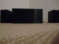
Um, some of them are 🙂 🙂 Here is my new build, completed tonight and undergoing initial listening with cheap bookshelves...cooking away at 1.2A bias.
Having built an Aleph a year or so back I think this thing would hold its own at the burning amp festival!
Listening to Ennio Morricone's "The Mission" soundtrack. It's something else!
Well, I just don't think it would attract any attention. For starters, it's not Class A.
Hugh
Um, some of them are 🙂 🙂 Here is my new build, completed tonight and undergoing initial listening with cheap bookshelves...cooking away at 1.2A bias.
Having built an Aleph a year or so back I think this thing would hold its own at the burning amp festival!
Listening to Ennio Morricone's "The Mission" soundtrack. It's something else!
Attachments
Or, Greg, increasing the lag comp to 68pF?
Would that have the same effect?
Not sure Hugh, but I don't think so.
My choke, which has 1.5m of wire (just unwound it and measured it properly today as I had to make some new ones), completely removes all signs of overshoot into pretty much any reasonable load.
To get the same stability with a miller cap required over 350pF! I'm sure we all would agree that 350pF of phase lag would sound pretty terrible.
This is of course assuming that less overshoot sounds better.
I think, believe it or not, that the output choke is the more sonically benign way of keeping this amp under control. It certainly sounds much better than I expected given that even the engineers say any more than 1uH is too much! It does alter the sound, but in a nice way. Makes it more tubey I reckon!
As with most things perhaps a compromise (like your current phase lag + small choke arangement) is the best? There's lots of room to experiment and fortunately your boards have room for it all.
A series resistor would normally be more like 2 - 8 ohms ( or less ) to effectively damp coil resonance
Perhaps, but a larger value may reduce the likelyhood of oscillating with certain loads, and allow the inductor to be decreased. Hint: this is a different mechanism than coil resonance. I think it may be more appropriate to use an RC snubber after the coil to dampen resonance if it is a problem. I remember AndrewT said something about this, but I don't think he provided any references. (I've only learned about this recently)
- keantoken
If you play around in spice with this you will see that it is the other way around . . . .
a smaller inductor need a smaller resistor to damp resonance
I just researched 3 possible scenarios that would work on my amp:
1.6uH + 2R
3.2uH + 4R
6.0uH + 8R
Each of these preceeded by a 0.1uF + 8R snubber and followed by 0.1uF directly across the o/p gives a near perfect square wave.
a smaller inductor need a smaller resistor to damp resonance
I just researched 3 possible scenarios that would work on my amp:
1.6uH + 2R
3.2uH + 4R
6.0uH + 8R
Each of these preceeded by a 0.1uF + 8R snubber and followed by 0.1uF directly across the o/p gives a near perfect square wave.
Here are 2 tips regarding this amp:
1) a VAS mosfet source degeneration resistor of about 20 ohms performs no useful function in my amp. It does not reduce OLG . . . but it does contribute to poorer stability when compared with lower values e.g. 5ohms or zero ohms. I settled for zero.
2) If you put a 500R resistor in series with your miller compensation cap, a given cap value will give better stability when compared to having no resistor in series.
I just did both these mods and the improvement was audible.
mike
Last edited:
Mike, I am not talking about perfect squarewaves. The function of the coil is to keep the amplifier from oscillating into certain loads. This may or may not have anything to do with the coil itself participating directly in the oscillation (more likely not). On the other hand, just because the amplifier resonates does not mean it is in danger of becoming unstable. My preference is to choose an output network combination that provides unconditional stability, and then add to that what's necessary to give a good square wave, not the other way around.
- keantoken
- keantoken
- Status
- Not open for further replies.
- Home
- Amplifiers
- Solid State
- JFET input, MOSFET VAS, LATERAL output = Perfect!!