Hello All ,
From the pass diy article " Ground Loops " , Kent English wrote :
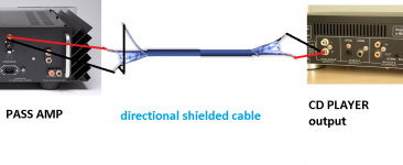
" If you ar running unbalanced cables, always run 2 conductor shielded wire .
(...) Shield ground should not be connected on the source end of the wire , only at the input component end "
Do I interpret it right just as is in the picture attacched or is it viceversa ?
Thank you .
From the pass diy article " Ground Loops " , Kent English wrote :
" If you ar running unbalanced cables, always run 2 conductor shielded wire .
(...) Shield ground should not be connected on the source end of the wire , only at the input component end "
Do I interpret it right just as is in the picture attacched or is it viceversa ?
Thank you .
Attachments
you got it right
NB that vice versa is sometimes even better

Really??
🙄
It's also a very bad idea! What really matters is having a very low shield/return resistance.
Bill Whitlock of Jensen Transformers writes:
In engineering terms, a high-performance cable for unbalanced audio should have low capacitance and very low shield resistance. A good example of such a cable is Belden #8241F. Its 17 pF per foot capacitance allows driving a 200 foot run from a typical 1 kOhm consumer output while maintaining a -3 dB bandwidth of 50 kHz. Its low 2.6 mOhm per foot shield resistance is equivalent to #14 gauge wire, which can significantly reduce common-impedance coupling.
I think Bill is referring to the common shield / 1 conductor variety of cable.
The earlier reference is to shield plus 2 conductors.
😎
The earlier reference is to shield plus 2 conductors.
😎
Yes, two conductor plus shield is better than coax... make sure the shield is a good one, though.
Though I would guess that if EMI is a particular problem in your area, the coax might be the lesser of the two evils since coax cables tend to have better shield characteristics...?
Though I would guess that if EMI is a particular problem in your area, the coax might be the lesser of the two evils since coax cables tend to have better shield characteristics...?
Last edited:
If I remember correctly from various readings of datasheets, etc. over the past few years, the shielding isn't some much due to whether it's a coax or a two conductor pair with separate shield, as it is with the particular cable. You have to look at the datasheet of the particular cable to see what the shield coverage is. Some are only ~70% range. The better ones will list a shielding of ~95% range or better. As you can see in the picture, some even use a full wrap aluminum shield, with a separate drain wire to connect the shield when desired.
This is all assuming that you are concerned with RF shielding in your area.
Peace,
Dave
This is all assuming that you are concerned with RF shielding in your area.
Peace,
Dave
No, there is nothing that says that a coax means good shield and non-coax means bad shield - but it seems as though applications that use coax cable seem to be a bit more intolerant of interference (and they can't be used balanced), and so coax cables usually have better shields.If I remember correctly from various readings of datasheets, etc. over the past few years, the shielding isn't some much due to whether it's a coax or a two conductor pair with separate shield, as it is with the particular cable.
Peace,
Dave
A foil shield will give 100% coverage but may not perform as well as a braid because of its higher resistance.
I know about what you speak stefanobilliani.
The main idea is to not have a current flow thru shield, can induce noise on signal. The current should pass thru an additional conductor.
This current is generated by ground diference between used equipments.
The main idea is to not have a current flow thru shield, can induce noise on signal. The current should pass thru an additional conductor.
This current is generated by ground diference between used equipments.
yes , my question was if it was correct to connect the shiled ( 2 conductors cable ) on the " amp " side <or> to the CDplayer side , since I was a bit confused with the "source " and "input component" terms .I know about what you speak stefanobilliani.
The main idea is to not have a current flow thru shield, can induce noise on signal. The current should pass thru an additional conductor.
This current is generated by ground diference between used equipments.
Anyway in my little pratical experience , it seems that 2 conductors + shield performs a bit better .
Thanks
In the Whitlock situation where there is an inter chassis voltage, it matters not that the coax using shield as chassis connection or using twinax with the second core (only) acting as chassis connection.
It's the resistance of the inter-chassis connection that generates the interfering voltage that gets mixed with the signal across the two conductors.
If the Audio Grounds inside both chassis are separated from the Chassis Safety Earth with some form of Disconnecting Network (DN), then a third inter-chassis wire or shield can be run that does not create an interfering voltage across the signal pair and does not create a hum loop.
But, those DNs can introduce their own problems.
Last edited:
Yet to get proper shielding the shield should be connected at end by a full 360 deg connections...
Yes, Fplugs on TV aerials and BNC on scopes/sig gens are examples.Yet to get proper shielding the shield should be connected at end by a full 360 deg connections...
It is mainly for the RF shielding, actually having only one end connected can be worse than both ends. To combat ground loop issues I have seen capacitors used in a ring inside the connector to connect one end and still get the RF shielding.
Chapter 2 in "Electromegnetic Compatability Engineering", H Ott covers this in intimate detail, and this article by K. Armstrong refering to IEC 61000-5-2 is interesting as are other articles by this gentleman.
http://www.diy-audio-kits.com/downl...pplying 61000-5-2 to cable shield bonding.pdf
Tony Waldon has some interesting articles on interference free audio, where using mesh grounds allows the control of ground loops.
We are mixing up three different terms and the solutions to these problems:
a] Ground loops - low return/shield resistance is good.
b] EMI - braided shield is good.
c] Higher RFI - foil shield is good.
The cable pictured in post #1 is not a good unbalanced audio cable.
a] Ground loops - low return/shield resistance is good.
b] EMI - braided shield is good.
c] Higher RFI - foil shield is good.
The cable pictured in post #1 is not a good unbalanced audio cable.
They are all part of the same problem, each problem and its associated solutions interact, they cannot be looked at in isolation. The type of shielding should be 100% coverage for best results, with 360° bonding at either end for RF, there needs to be connections at either end for magnetic shielding, and connecting a both ends then adds the ground loop. A total engineering solution has to be found for all aspects of shielding, and the best way of achieving this would be to consider the whole system as one integrated unit, not easy though when you have to use different components from different manufacturers, as you have multiple protective earth connections.
Copper braid with foil provides the best quality shielding giving a full 100%, braid on its own is quite often around 70-80% coverage, but is still effective, foil on its own is for less noisy installations, and is the cheaper option, usually using aluminium foil.
The best method is to carry the signal through two wires internaly and connect the shield to the metal case at both ends, ie try to isolate the return current from the shield currents and noise.
EMC Compliance Club
I must be nuts for likeing RG-58.
I have never had problems with RFI, but groundloops I have found many of. My normal approach is a few wires with crocodile clips on each end, used to connect up ground in various configurations... most often the fix is as simple as connecting the two input grounds to each other.
I have never had problems with RFI, but groundloops I have found many of. My normal approach is a few wires with crocodile clips on each end, used to connect up ground in various configurations... most often the fix is as simple as connecting the two input grounds to each other.
The reason why this works is documented in these two excellent articles, all the problems and techniques discussed are scalable, from large audio installations to a small home system . The pertinent points similar to your solution can be found in the first link in paragraph 2 of section 2 introduction and section 4 A note on Ground Loops.
Designing for Interference-free Audio System Components
A Practical Interference Free Audio System (Part 2)
Designing for Interference-free Audio System Components
A Practical Interference Free Audio System (Part 2)
this is why I build and recommend that the Main Audio Ground (MAG) be constructed from a bolt and solder tags.............. but groundloops I have found many of. My normal approach is a few wires with crocodile clips on each end, used to connect up ground in various configurations... most often the fix is as simple as connecting the two input grounds to each other.
It can be experimented with till the cows come home.
If you think you need it, add a nut to keep the joints in the assembly airtight.
personally i'm not a big fan of connecting it at one end only with shielded pair; imo if you have designed your equipment properly you should be able to connect it at both ends, the chassis/shield should both be at the same potential anyway (earth directly at the IEC) if you have done your job right and it should not be directly connected to signal ground so only shield currents should flow through it. just my opinion of course and with commercial gear not always possible, but as diyers we have the power to make sure grounding is consistent
- Status
- Not open for further replies.
- Home
- Amplifiers
- Pass Labs
- Ground Loops - Article question , confirmation