I understand that this may be very impractical, but i'm trying to design a battery powered tube amp. I just want to verify that i'm thinking things through correctly.
So my idea is to use a 12v battery source and construct a square wave oscillator out of BJT power transistors.
The amp i have designed uses one 12AX7 and one 6V6GT.
12AX7 Filament = 6.3v X 300mA = 1.89W
12AX7 Max Dissipation = 1W
6V6 Filament = 6.3v X 450mA = 2.84W
6V6 Max Dissipation = 12W
So if you add this all together, in a perfect world, you get 17.73W as the amount of power that the amplifier is drawing when it is under max load. However, power is lost through transformers and other passive components so realistically i would think that 20W would be a safe assumption for the max amount of power this amp will draw. My choices for a transformer are either 20Va or 36Va. The last thing i want to do is overload this power supply so i am going to pick the 36Va transformer, just to be safe.
Each transistor will oscillate 12Vpp making the the square wave 24Vpp 36Va is equal to 36w in most cases, so 36 / 12 = 3A. So i need to pick BJT power transistors that can handle 3A of current. Now i have a power supply that can deliver 115v at 36W which feeds the tube amp a 60hz square wave for power. The converts it to the 300+ volts i need and the full wave rectifier makes DC out of the square wave. I shouldn't need that much filtering in the tube amp itself because a rectified square wave should be almost perfect DC.
Does all of the that sound logical to you guys? It's pretty impractical to go from DC to AC, and then back to DC. But building a efficient DC-DC converter to supply an amp that is already not efficient seems pointless. Also the parts for a DC-AC-DC converter are cheaper than a DC-DC converter and take up less space.
I would like to know what everyone thinks of this 🙂
If it was me, I'd use a lower voltage and find some lower voltage tubes.
Then I'd buy some cheap 6s Lipos from HobbyKing at 22V each, and string about 5 in series to give me 110V of pure DC power.
To charge them I'd either buy the proper charger(s) or build some boards with 4.2V zeners to prevent any cell from exceeding that voltage. Charging of Lipos is important because overcharging them will burn your house down, as it has done to others.
For filaments you just need a 2s Lipo with some voltage drop - perhaps through diodes or a dropper resistor.
Using this method you will probably end up with the best PSU in the world and the amp - if happy at 110V will sound fantastic.
An externally hosted image should be here but it was not working when we last tested it.
An externally hosted image should be here but it was not working when we last tested it.
my 6v6 amp .and battry power supply.mosfets swiched in square wave 12vp-p.+b...is 250 v.6aw8 is driver for 6v6 .sound more musical.😱no noise on speker frome this power supply ....
Greetings Hooman from a very soggy Binghamton, NY!
Can you post the circuit to your amplifier?
Thanks,
Ray
Can you post the circuit to your amplifier?
Thanks,
Ray
Or, you could use so-called "space-charge" tubes, which were designed for car radios and use 12v for both the heater and the plate. I don't know what kind of wattage one could expect from such things, but it is an option.
Or, you could use so-called "space-charge" tubes, which were designed for car radios and use 12v for both the heater and the plate. I don't know what kind of wattage one could expect from such things, but it is an option.
Most used something called a vibrator to make the high voltage for the plates.
OT
hey Maxro I guess being an FSM fan is a prerequisite to living in the "least happiest city in Canada-" 🙂
hey Maxro I guess being an FSM fan is a prerequisite to living in the "least happiest city in Canada-" 🙂
Most used something called a vibrator to make the high voltage for the plates.
No really, space charge tubes need all of 12v at the plate, though they perform better with 24v. max of 30v.
unfortunately the 12al8 seems to be the big daddy power space charge tube at about 1/2w.
No really, space charge tubes need all of 12v at the plate, though they perform better with 24v. max of 30v.
unfortunately the 12al8 seems to be the big daddy power space charge tube at about 1/2w.
Oh, my experience was a long time ago working on antique car radios. I can't recall seeing those (space charge tubes), but I do remember replacing a lot of vibrators in those old radios.
How about using a pair of MAX1771's. Yes, I know you said that DC - DC would be pointless, but I think that's cheaper. With proper FET and inductor it should be capable to deliver required power. Nixie HV Switching PSU check this page if you are interested.
So if you add this all together, in a perfect world, you get 17.73W as the amount of power that the amplifier is drawing when it is under max load.
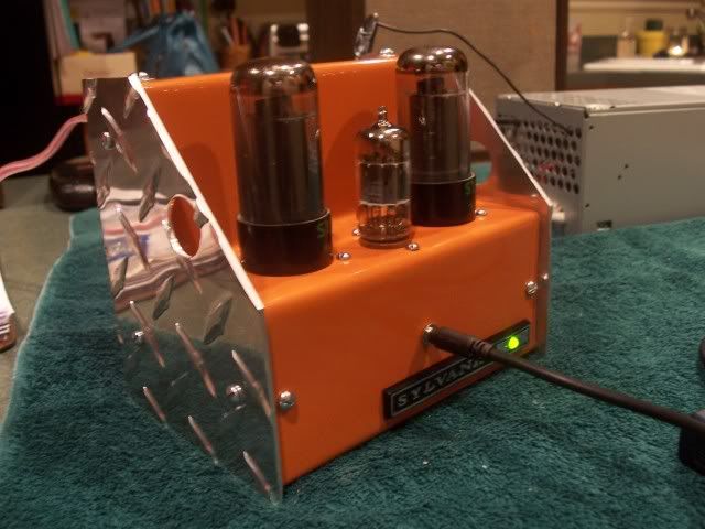
My stereo SE 12AX7/6V6 battery powered amp draws 34 watts at idle so your numbers are pretty good. Here's a shot of it using a computer power supply for initial testing.
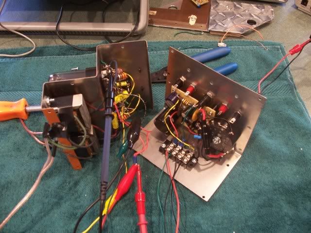
Here's the guts.
Last edited:
- Status
- Not open for further replies.
- Home
- Amplifiers
- Tubes / Valves
- Battery Powered Tube Amp