> As the sim showed even variations of 5% in hfe didn´t increase THD considerably.
Unless we have made some very stupid mistakes.......
We have tried all combinations bu changing each of Q1 to Q4 by 5%. Irrespective of what Q2 & Q3 does, every time when we change Q4 by 5% and keep Q1 unchanged, or vice versa, we get THD 0.019%. I also find it difficult to understand, but I have no time to figure it out right now.
Patrick
Hi,
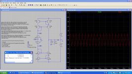
for a higher precision of the THD analysis the command .plotwinsize=0 should be set.
This switches off the data compression feature of LTspice.
EUVLs sim missed on this command and I was able to verify his high THD-figures by removing this command from my simulation.
In #62 I included the LTspice file to verify or falsify the sims. As one can see, I used the same models and variations.
Funny thing... with the plowinsize command set and Q1 (or Q4 in EUVLs schematic) varyed, the THD-figures were the lowest of all transistor combinations (0.000314% -110dB). 😕🙄😀😱 🙂
🙂
jauu
Calvin
for a higher precision of the THD analysis the command .plotwinsize=0 should be set.
This switches off the data compression feature of LTspice.
EUVLs sim missed on this command and I was able to verify his high THD-figures by removing this command from my simulation.
In #62 I included the LTspice file to verify or falsify the sims. As one can see, I used the same models and variations.
Funny thing... with the plowinsize command set and Q1 (or Q4 in EUVLs schematic) varyed, the THD-figures were the lowest of all transistor combinations (0.000314% -110dB). 😕🙄😀😱
🙂 jauu
Calvin
Last edited:
You are right with Spice. We can confirmed that.
So at least we have resolved that difference.
🙂
Patrick
So at least we have resolved that difference.
🙂
Patrick
Hi,
what differences? We were pleasantly discussing alternatives, weren´t we?
Now only the Tube-fraction is missing on their SEN-version here 😉
jauu
Calvin
what differences? We were pleasantly discussing alternatives, weren´t we?
Now only the Tube-fraction is missing on their SEN-version here 😉
jauu
Calvin
I have 2 PCBs of Sen & Cen to spare.
If you promise to build and compare with your BJT version, I'll send you for free.
Interested ?
We shall do some more work on Joachim's, based on 4-BJT Wilson Mirrors.
Both in Sim and in hardware.
Schoenen Gruss,
Patrick
If you promise to build and compare with your BJT version, I'll send you for free.
Interested ?
We shall do some more work on Joachim's, based on 4-BJT Wilson Mirrors.
Both in Sim and in hardware.
Schoenen Gruss,
Patrick
We can send them all to Jan Didden for audition.....
🙂
Patrick
I have an even better idea. I will be at Stuarts' house with a few more very critical and accomplished listeners mid-October. We can do an informal (or even formal) listening session then. If Stuart has time, of course. Never know with those VP's 😉
jan
I do not plan to go into competition. Patrick, your design is simple, elegant and efficient.
A shoot out at Jan´s place would be fun though if he agrees.
A shoot out at Jan´s place would be fun though if he agrees.
> I do not plan to go into competition.
Was never meant to be.
I have no problems at all which design comes out "on top".
It will probably be a subjective preference in the end.
They are all elegant designs, and have very low distortions anyhow.
🙂
Patrick
Was never meant to be.
I have no problems at all which design comes out "on top".
It will probably be a subjective preference in the end.
They are all elegant designs, and have very low distortions anyhow.
🙂
Patrick
We have spiced a modified version of Joachim's circuit with complementary input FETs, Wilson current mirrors and fixed rails.
With 1mA input and 2.7k R_iv, THD is 0.039%.
The model used identical BJTs in both current mirrors (i.e. perfect match).
We'll test hardware when proto PCB is ready.
Patrick
.
With 1mA input and 2.7k R_iv, THD is 0.039%.
The model used identical BJTs in both current mirrors (i.e. perfect match).
We'll test hardware when proto PCB is ready.
Patrick
.
Attachments
Last edited:
THD
hi Patrick,
THD is 0.039% or 0.0039%?
Thanks for sharing your version of this great IV!
best regards,
Piersma
hi Patrick,
THD is 0.039% or 0.0039%?
Thanks for sharing your version of this great IV!
best regards,
Piersma
You are right. Typing mistake. 0.0039% for CEN CM IV.
CM stands for current mirror.
Under same conditions in Spice, CEN IV (floating supply) is 0.0019%.
But probably a better current mirror will imprive things for CEN CM.
Patrick
CM stands for current mirror.
Under same conditions in Spice, CEN IV (floating supply) is 0.0019%.
But probably a better current mirror will imprive things for CEN CM.
Patrick
That does not look too bad. Have you tried my single ended cascoded version too ?
Distortion should go down when you use the helper transistors. Also try differential feedback by connecting 50kOhm to 100kOhm resistors from the inputs of the mirrors to the outputs.
Distortion should go down when you use the helper transistors. Also try differential feedback by connecting 50kOhm to 100kOhm resistors from the inputs of the mirrors to the outputs.
- Home
- Source & Line
- Digital Line Level
- Zen -> Cen -> Sen, evolution of a minimalistic IV Converter