Dear All,
I started to play with the Arduino microprocessor (Had not use any microprocessor before), and I was amazed to find out how easy is to implement things using it.
I was thinking, how difficult can be to make a controller for the F5 ? My idea is to spit my project in two phases:
1) Passive: Arduino reads temperatures, offset, and bias and show them on a display or gives alarms.
2) Active: Arduino reads all the parameters, protects the speakers from excessive DC offset and allow to modify the bias. I would do first with an algorithm to be used with speakers disconnected and if it's really reliable it could be done real time.
This would be fun for listening tests and to find the sweetest spot. The F5 was selected only because I am familiar with the circuit and with the behavior while setting the bias.
Here is where my basic electronic ignorance come into the game, and I would appreciate to have some hints on what parts or circuit should I use for:
a) Measuring a voltage that is not between 0 and 5V but between 23V and 24V.
b) develop a controlled resistor.
c) measuring the DC bias
I am not asking for ready made things, just to be pointed where to start my readings.
Any collaboration in this project is welcome !!!
By the way, I found out that having a display on a device can largely increase the WAF of the device. You can program the amp to say sweet thing to your best half, any time it powers up. No commercial amp can do that !!! They will love it.
Best Regards,
Davide
I use a PIC micro for checking DC offset and for power up delay on the speaker relay.
If I see 500ms of DC I assume there is a fault and disconnect the speaker relay.
You can use an a2d converter for looking at voltages.
You could use scaling resistors to look at higher voltages but you would lose accuracy that way.
If I see 500ms of DC I assume there is a fault and disconnect the speaker relay.
You can use an a2d converter for looking at voltages.
You could use scaling resistors to look at higher voltages but you would lose accuracy that way.
Hi Nikon
IMO change the tread title to a Useful and Funny...
I am to green to realy help but will be watching
At present I have one transistor for power up (momentary Push Button)
One transistor timer for Thermistors By pass.
NTE 7100 for speaker protection which does delay speaker conection
DC ofset protection and speaker disconect when power down (before thump)
It could also do overcurrent but I have not implemented that.
I was going to try for overcurrent protection by reading the voltagge accross the source resistors with a couple of comparators but not there so far.
SO I will be watching this.
To have all this on a single board (NTE7100 obsolete) is a great idea.
All the best
Al
I've often thought about adding miscroprocessors to amps, but then I am stumped by how to realy isolate the clock noise etc from the digital side going to the amp side.
Nikon - awesome. Arduino is a lot of fun. I suggest:
Read the API for libAVR. I think most of the AVR variables and functions can be accessed from inside the 'Wiring' and 'Processing' based IDE they provide you for programming your Ardy, or you can code in C/C++ and compile with the IDE. Their basic implementation is very limited. It works and is easy, but there's so, so, so much more your ATMEGA chip can do.
Get the big, fat manual for whatever chip your Ardy has on it. You're going to be using the ADC a lot, and you'll find out by reading the manual exactly how limited and slow the Arduino IDE's ADC API is. You can achieve 8-bit sampling at about 70kHz on the ATMEGA168 if you get at it directly using AVR's functions. Also, there are... 3? Hardware and ...3? timer interrupts available so you don't have to use the 'delay' function (which is really just a "wait X cycles" loop) and I2S and SPI etc etc etc interfaces available for talking to DAC's and DSP's and blahblahblah
Makes me want to buy another. Mine got blown up when I lent it away to be used in a highschool production controlling lights :'(
Thanks for the support! The display and remote command part with Arduino, I already figured out for my DAC. Where i am lost is the measurement of the voltages not referenced to zero and the offset.
Davide
Davide
very cool Davide!! you could perhaps use LED's for the bias (variable resistor) and control these with voltage?
Davide,
It sounds like real fun. 🙂
A personal opinion if I may :
A uP based solution will have all the flexibility in the world, and you can change things easily even after the hardware is in place.
In that sense it is hard to beat.
We had a similar discussion at work about a safety concept for a semiconductor manufacturing equipment a few years back. The consequence of a crash is over a million Euro damage. Not as bad as in a nuclear plant, but also the company's reputation is at stake in such a crash. After a long discussion of over three months with more than 20 conceptual system architects involved, we finally went for a safety solution which is purely mechanical and electrical hardware based (crash barriers, safety traps, electrical hard wired interlocks, ...).
I am sure you also know a few such examples at work.
If I were to choose, I think I'll still go for the hardware solution.
If anything, I don't think I want a MHz oscillator near my analog Amp.
😉
Patrick
Patrick,
I agree with you in most of the things. My goal is mainly to learn how to do it, and I wanted to take the challenge to write the setting algorithm, so that it would always converge to zero offset.
For the ultimate built I would also go for a resistor, but during the tuning phase (of F5 or any circuit that needs trimming) a setup like this would be very useful. I think I have an almost zero musical memory, so for me it's very hard to compare two settings, even if I just have to hook the voltmeter and change only the bias, let's say a 15 minutes job. Having the facility to do it in few second would help to find the sonic sweet spot, at least I hope.
But anyway, I would test it on PC speakers for long time before connecting to serious speakers.
D.
Ok, just to let you know I did not drop the idea: temperature measurement (easiest part). Any suggestion for floating voltage measurements? The Arduino measure between zero and 5 V.
Thanks,
D.
Thanks,
D.
Just transfer the voltage down towards earth. e.g. In the pic below, the voltage across R2 is 1 volt higher than that across R11 in the existing circuit. The voltage across R3 is the same as that across R2 and should be easy to measure. The capacitor is optional, just smooths the result to let you measure average instead if instantaneous current through the output device.
Attachments
Thanks!! That looks easy. Two questions: what is the role of the led? Os thos going to affect the bias in any way?
Then, let's optimize the thing a bit: arduino can measure 1024 voltage levels, either between zero and 5 V or between zero and a reference voltage.
I want to measure both the bias and the offset. In order to use all the dynamic range of the arduino I can use, let's say 1 V reference or plofy the bias voltages. What's the best way to go?
Thanks,
Davide
The LED is to make sure the transistor is always on. The voltage drop across the LED is about 1.7V and the voltage difference between the base and emitter of the transistor is about 0.7V. So the voltage across R2 is about 1V gewater than the voltage across R11 (in the existing circuit).Thanks!! That looks easy. Two questions: what is the role of the led? Os thos going to affect the bias in any way?
The current through R1 and the LED does reduce the current through the top output MOSFET by about 2mA, which I thought insignificant.
I would choose 5V, rather than a lower reference voltage. The circuit below lets you monitor Bias current and DC offset voltage. According to my simulator, outputs will be something like this:Then, let's optimize the thing a bit: arduino can measure 1024 voltage levels, either between zero and 5 V or between zero and a reference voltage.
I want to measure both the bias and the offset.
Current:
0A => 4.82V
2.5A => 1.31V
DC offset:
0V => 2.21V
+2.5V => 4.34V
-2.5V => 0.08V
"plofy"?😕... let's say 1 V reference or plofy the bias voltages.
Attachments
I'll put things together as soon as i come back home. 🙂
After I perfectioned the data acquisition, the real fun comes.
D.
After I perfectioned the data acquisition, the real fun comes.
D.
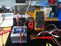
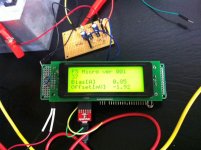
Progress Report
So,
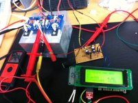
Getting cuter and cuter. Here two images. I have to add the temperature reading that I did in a separate program.
I have two problem/questions:
1) I was mistaken, my arduino reads voltages between 0 and 3.3V as I have a 3.3V processor. So I think I have to replace some resistors to account for that.
2) The calibration is a bit tricky, and one issue that I see is that the readings depends also on the rail voltages. Now I am testing the thing with two SMPS units that are regulated, but if I move to the real amp, the rails could move a bit with the mains.
3) If I want to use the circuit with Toshiba mosfet, that have 0.22R for degeneration, should I change anything ? (beside the calibration)
4) What about if rail voltages are lower, like 16 V should I change anything ?
Can I have the LT spice file of the circuit, it would help me to understand how it works (still not 100% clear to me, poor ignorant).
Thanks,
Davide
Thanks,
So,
Getting cuter and cuter. Here two images. I have to add the temperature reading that I did in a separate program.
I have two problem/questions:
1) I was mistaken, my arduino reads voltages between 0 and 3.3V as I have a 3.3V processor. So I think I have to replace some resistors to account for that.
2) The calibration is a bit tricky, and one issue that I see is that the readings depends also on the rail voltages. Now I am testing the thing with two SMPS units that are regulated, but if I move to the real amp, the rails could move a bit with the mains.
3) If I want to use the circuit with Toshiba mosfet, that have 0.22R for degeneration, should I change anything ? (beside the calibration)
4) What about if rail voltages are lower, like 16 V should I change anything ?
Can I have the LT spice file of the circuit, it would help me to understand how it works (still not 100% clear to me, poor ignorant).
Thanks,
Davide
Thanks,
Attachments
- Status
- Not open for further replies.
- Home
- Amplifiers
- Pass Labs
- F5 Micro (A useless but funny project)