hello,
what are the modern incarnations of Jean Hiraga "Le Monstre" published in L'Audiophile n°27 (ancienne série) in Feb. 1983 ?
what are the modern incarnations of Jean Hiraga "Le Monstre" published in L'Audiophile n°27 (ancienne série) in Feb. 1983 ?
Attachments
Last edited:

Or a copy of Nelson's amp 😛
Géo
The profet was published quite a few years before the F5 😀
Besides they are not the same, look at the feedback paths.
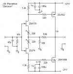
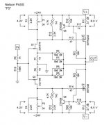
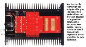
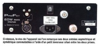
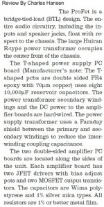
Or maybe Selectronic licensed the J.M. Plantefève "Zenotron" schematic and industrialized a deluxe version with a R-Core transformer and 8 x 10,000µF in the power supply. Jean Hiraga himself reviewed the Selectronic ProFet.
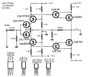
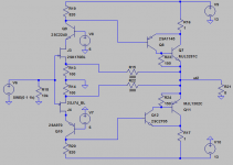
Wait a moment. This is a mono amplifier. I count 4 MOSFETS in total. It is a bridged tied load "Zenotron" incarnation with a floating power supply.
Wait a moment. This is a mono amplifier. I count 4 MOSFETS in total. It is a bridged tied load "Zenotron" incarnation with a floating power supply.
Attachments
Last edited:
I'm looking to other schematics like "Zenquito" or "Buzquito" (or Mosquito). They feature a symmetric voltage amplification stage between the FET input stage and the power MOSFETS. Because of the additional phase inversion, the MOSFETS are now source followers. Shall we say these are modern incarnations of Hiraga "Le Monstre" ? If not, what is their generic name ?
I like R21 + R22 in the F5 schematic! Soft voltage
limits by way of soft current limits. 3 fewer parts
for this function than mine, and might work better.
I was using 4 Zeners and a resistor in feedback.
Voltage knee a little sharper than current knee.
and capacitance of the Zener stack is variable.
I'll give Nelson's way a try, see what happens.
limits by way of soft current limits. 3 fewer parts
for this function than mine, and might work better.
I was using 4 Zeners and a resistor in feedback.
Voltage knee a little sharper than current knee.
and capacitance of the Zener stack is variable.
I'll give Nelson's way a try, see what happens.

How I can I convert Hiraga's "LeMonstre" to a CSPP version (cross shunted push pull)?
go to post #1 about
http://www.diyaudio.com/forums/solid-state/146586-conversion-hiragas-le-monstre-circlotron.html
If I had a solution to this, I am happy.
go to post #1 about
http://www.diyaudio.com/forums/solid-state/146586-conversion-hiragas-le-monstre-circlotron.html
If I had a solution to this, I am happy.
Very nice simulation ! What transistor models are you using ? The THD pattern looks very nice, like in a fully optimized amplifier. Are you sure you have not tweaked the models, making them more symmetric (or asymetric maybe) than they should ? By the way, I'm very curious to see the power supply rejection.Here is something I recently started to play with based on the old le monstre. I'ts in no way optimized but it is a start.
That is a copy of Selectronics Profet...
Can someone explain me what the poster meant here? Did he/she mean that Nelson Pass copied Profet for F5?
Can someone explain me what the poster meant here? Did he/she mean that Nelson Pass copied Profet for F5?
Read Mr Pass's F-5 articles, I believe that's where that comment comes from. (Made by Pass himself) It is similar, no caps in the signal path, etc, but as Mr Pass also states, "The devil is in the details" and there are more than a few of them separating these two amps.
Russellc
Very nice simulation ! What transistor models are you using ? The THD pattern looks very nice, like in a fully optimized amplifier. Are you sure you have not tweaked the models, making them more symmetric (or asymetric maybe) than they should ? By the way, I'm very curious to see the power supply rejection.
I use a few different models found on this board and for the outputs models from bob cordell.
Haven't begun in earnest with the PSRR as I'm using ideal voltage sources for biasing the cascodes.
Only voltage gain of x4. Hard not to plot a clean 1stW with that much feedback.
I know the voltage gain is low but there is no point driving the amp to more than clipping. The open loop gain is about 38db the closed loop gain 12db so its not more than about 25db used for feedback.
This approach could be the rightHow I can I convert Hiraga's "LeMonstre" to a CSPP version (cross shunted push pull)?
go to post #1 about
http://www.diyaudio.com/forums/solid-state/146586-conversion-hiragas-le-monstre-circlotron.html
If I had a solution to this, I am happy.
https://www.diyaudio.com/community/threads/i-call-it-infinitron.270239/
- Home
- Amplifiers
- Solid State
- modern incarnations of Hiraga Le Monstre