Hi everyone,
As previously said in other posts, I've already designed and built 2 Front Loaded Horns with 15'' drivers which sound great ! Thanks so much David for releasing and always improving HORNRESP.
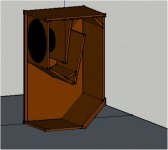
To pursue my bass quest, I'm planing to build up 4 others bass bins with 18'' drivers but this time with Rear Loaded Horn. The aim is to get proximity response and bass pressure feeling with the direct radiating driver combined with the horn's long range abilities - not looking for a wide range of frequencies as usually in HiFi designs : 35-110Hz should be enough!
Some informations : Drivers are Precision Device PD186 / The design below is for a stack of 4 bins in half space.
First, I'm not sure to use HORNRESP correctly in case of a Rear Loaded Horns... 😕
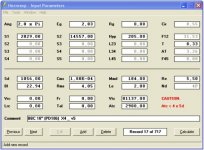
- regarding the 4 drivers in parallel in hornresp, to get the sensitivity of each box + 6 dB for the full stack, should I fix Eg = 2.83 v or 2.83x4=11.32 v?
In other words Eg=2.83 v gives the sensitivity of the complete stack (4 speakers) or hornresp assume that 2.83 v is provided to each speaker ?
- is a T=0.33 not too small… what are the incidences on the results?
- Vtc/Atc… I chose for Atc, the smallest section crossed by the waves going through the horn (Atc = S1). So that Atc also defines the limit of Vtc (minus the driver volume) - is that right?
About the results :
SPL looks correct to me even if some oscillations of +/-3 dB appears in the frequencies range (assuming that half space calculations is a bit rude). But what about the other results… some interpretations would help me a lot!
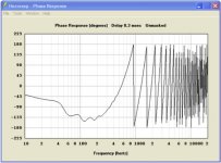
- Delta Phase response < 180° but pretty close to boundaries!!
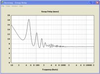
- Group Delay??
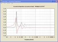
- Acoustical Impedance??
- To get the combined response of the direct driver and the horn what length/distance should be enter in hornresp as the Horn Mouth and Driver are in the same plan? L=0m?
- Any other important recommendations?
Many thanks to everyone for this forum and the help provided… 🙂
Oliver
As previously said in other posts, I've already designed and built 2 Front Loaded Horns with 15'' drivers which sound great ! Thanks so much David for releasing and always improving HORNRESP.
To pursue my bass quest, I'm planing to build up 4 others bass bins with 18'' drivers but this time with Rear Loaded Horn. The aim is to get proximity response and bass pressure feeling with the direct radiating driver combined with the horn's long range abilities - not looking for a wide range of frequencies as usually in HiFi designs : 35-110Hz should be enough!
Some informations : Drivers are Precision Device PD186 / The design below is for a stack of 4 bins in half space.
First, I'm not sure to use HORNRESP correctly in case of a Rear Loaded Horns... 😕
- regarding the 4 drivers in parallel in hornresp, to get the sensitivity of each box + 6 dB for the full stack, should I fix Eg = 2.83 v or 2.83x4=11.32 v?
In other words Eg=2.83 v gives the sensitivity of the complete stack (4 speakers) or hornresp assume that 2.83 v is provided to each speaker ?
- is a T=0.33 not too small… what are the incidences on the results?
- Vtc/Atc… I chose for Atc, the smallest section crossed by the waves going through the horn (Atc = S1). So that Atc also defines the limit of Vtc (minus the driver volume) - is that right?
About the results :
SPL looks correct to me even if some oscillations of +/-3 dB appears in the frequencies range (assuming that half space calculations is a bit rude). But what about the other results… some interpretations would help me a lot!
- Delta Phase response < 180° but pretty close to boundaries!!
- Group Delay??
- Acoustical Impedance??
- To get the combined response of the direct driver and the horn what length/distance should be enter in hornresp as the Horn Mouth and Driver are in the same plan? L=0m?
- Any other important recommendations?
Many thanks to everyone for this forum and the help provided… 🙂
Oliver
Attachments
-
 BBC.RLH118_shape.jpg28.8 KB · Views: 1,001
 -
 BBC.RLH118_Hornresp_param.jpg53.5 KB · Views: 1,030
 -
 BBC.RLH118_Hornresp_SPL.jpg112.2 KB · Views: 984
 -
 BBC.RLH118_Hornresp_phase.jpg45 KB · Views: 906
 -
 BBC.RLH118_Hornresp_AcImpedance.jpg120.2 KB · Views: 850
 -
 BBC.RLH118_Hornresp_GpDelay.jpg38.4 KB · Views: 247
 -
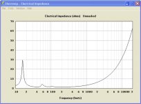 BBC.RLH118_Hornresp_Impedance.jpg102.3 KB · Views: 260
35-110 seems like a pretty large range of frequencies for a subwoofer....check out the TH-18 possibly, it is geared towards live sound but it covers the range you want, and was originally designed for the PD1850 driver.
And use 2.83 not 2.83 x 4....
Any reason for wanting a rear loaded horn as opposed to a tapped horn?
And use 2.83 not 2.83 x 4....
Any reason for wanting a rear loaded horn as opposed to a tapped horn?
combind responce could be set as 0.
looking at the input data the mout area = verry big 1.5 m2=~3'*5'
edit/ i see its 4 cabs.
if u use 4 cabs ,just use 1 paralel speaker @ 0.5 pi(same result)
looking at the input data the mout area = verry big 1.5 m2=~3'*5'
edit/ i see its 4 cabs.
if u use 4 cabs ,just use 1 paralel speaker @ 0.5 pi(same result)
Last edited:
for a f3 of 35 hz increase the pathlengt by 70 cm.
side note ,rlh always have a big dip in this case ~ 100 hz(this is why people think they go real low,but in reality they fall of @ 50 or so)
side note ,rlh always have a big dip in this case ~ 100 hz(this is why people think they go real low,but in reality they fall of @ 50 or so)
Thanks for your answers,
Anything to say about the Group Delay / Acoustical Impedance??
Mainly because I've never listen a Tapped Horn in PA conditions yet - whereas I heard a lot of RLH and I really like the pressure effect of the direct radiator at about the height of the thorax. Shaking style 😀 But the Tapped Horn idea is very interesting and maybe for my next build! wait and ear... but I want to ear first - according to my simulations, my last Folded horns where supposed to cover 35-100 Hz and I've never eared anything below 50 Hz... probably because the speakers and T&S parameters didn't describe properly the real response under 80 Hz. So that I decided to build new RLH with 18'' and more particularly for the PD186 because of their response in BF.Any reason for wanting a rear loaded horn as opposed to a tapped horn?
Hard to find 70cm with this horn path... can you tell me more about the falling @ 50Hz... for me the 100Hz dip still a myth...for a f3 of 35 hz increase the pathlengt by 70 cm.
side note ,rlh always have a big dip in this case ~ 100 hz(this is why people think they go real low,but in reality they fall of @ 50 or so)
Anything to say about the Group Delay / Acoustical Impedance??
here is your fr sim.
i moddeled a double flared rlh many years back, these were huge cabs and went lower than the usual scoops.
im trying to find the sim.
the dip is caused where the back wave meat's front wave .

i moddeled a double flared rlh many years back, these were huge cabs and went lower than the usual scoops.
im trying to find the sim.
the dip is caused where the back wave meat's front wave .
Sorry for the delay... few days off!
Thanks a lot for your answer epa and especially for the sim.
So as I've also seen on some measurements, the 145Hz dip of the back & front waves crossing is real but high enough to be out of the working frequency range. By the way your sim shows a nicer SPL than I expected - even if the FR is reduced to 45-100Hz - but are you sure that the EXP horn you simulated is equivalent to the HYP parameters I used?
Nice 😀 but what do you precisely mean by the impulse response?everything else looks fine,i like the impulse responce.
first have to say the dip wil be @ 110 if you extend your horn path 70 cm and @ 140 or so in your example.
hyperbolic or exponential doesn't make a difference.
in the pic i plotted the black line =exp and the grey line= hyp.
as you can see no difference
impulse is how long it takes the box to respond and to quiet down after a signal.
so a tight sound if you will in your case.

the good news is the pd won't exceed x-limit @1000 watts @30 hz.
and yes verry efficient design indeed.
those pd drivers are beasts😀
hyperbolic or exponential doesn't make a difference.
in the pic i plotted the black line =exp and the grey line= hyp.
as you can see no difference
impulse is how long it takes the box to respond and to quiet down after a signal.
so a tight sound if you will in your case.
the good news is the pd won't exceed x-limit @1000 watts @30 hz.
and yes verry efficient design indeed.
those pd drivers are beasts😀
Last edited:
hi Mr EPA
i want to know velocity out of horn is 1.4 m/s that is ok???.
nomar how many met/ ????
please coment
thank
i want to know velocity out of horn is 1.4 m/s that is ok???.
nomar how many met/ ????
please coment
thank
Hornresp MH
Hello, my friends, my name is Robson, and I come through this post to ask you something; COULD ANYONE HERE AND HELP SIMULATE A SYNERGY HORN using HORNRESP?
Hello, my friends, my name is Robson, and I come through this post to ask you something; COULD ANYONE HERE AND HELP SIMULATE A SYNERGY HORN using HORNRESP?
- Home
- Loudspeakers
- Subwoofers
- 18'' Rear Loaded Horns designed with HORNRESP - help needed!!