I might be misunderstanding the part numbering on the rectifiers. It was my understanding that if the part ended with a "D" it meant it was a "doubler" aka a dual series rectifier. That would mean it would not matter if it was a FED or FEP part as long it ended with a letter "D"? Look to the right side of the linked data sheet.
http://www.fairchildsemi.com/ds/FE/FEP16DTD.pdf
http://www.fairchildsemi.com/ds/FE/FEP16DTD.pdf
To be honest, my experience level is very low. I can only tell you I succesfully replaced the FED16BT with FED16CT, maybe someone else can help you out on this.
Otherwise, just order the parts from Jaime (jandrelectronix@aol.com), he can answer these questions. His prices are good and he can also sell you cosmetic parts (such as gold screws amongst other things) at great prices if you want to improve the cosmetics of your amp.
Otherwise, just order the parts from Jaime (jandrelectronix@aol.com), he can answer these questions. His prices are good and he can also sell you cosmetic parts (such as gold screws amongst other things) at great prices if you want to improve the cosmetics of your amp.
At the time when the earlier SS amps were produced, the polarity/configuration of the dual diode was signified in the prefix.
FEN = negative center tap
FEP = positive CT
FED = doubler
Now, they use FEP for the prefix and the configuration is signified by the letter (or lack thereof) after the T in the part number.
Nothing after the T indicates that it's a positive CT rectifier.
An A after the T means that it's a negative rectifier.
A D after the T means it's a doubler.
The letter between the numerals and the T indicates the rated voltage. Lowest voltage (50v) = A.
At the time when the earlier SS amps were produced, the polarity/configuration of the dual diode was signified in the prefix.
FEN = negative center tap
FEP = positive CT
FED = doubler
Now, they use FEP for the prefix and the configuration is signified by the letter (or lack thereof) after the T in the part number.
Nothing after the T indicates that it's a positive CT rectifier.
An A after the T means that it's a negative rectifier.
A D after the T means it's a doubler.
The letter between the numerals and the T indicates the rated voltage. Lowest voltage (50v) = A.
Another great bit of information. Thanks Perry!
Perry's right, You will find if you look at the polarity of the diodes in each different device N,P, and D that the diodes change direction with respect to polarity or usage. You will see anodes together or cathodes together or in the case of the D device they appear to have a single direction to the left or right depending on weather your looking at the anode or the cathode direction.
Almost any replacement will work for the N, and the P devices, it's the D device that is rather hard to come by in anything but original parts and even they are somewhat difficult to locate at times, and a general replacement from other manufacturers has not been found by me over the years I have been replacing them. The D's failure rate is like 10+ times that of the P's and N's.
Hope this helps some...C🙂
Sorry for the thread jacking we were talking about op-amps....
Last edited:
Hey its okay 1moreamp - all this is very useful information and I don't consider it thread jacking. Please continue sir!
Almost any replacement will work for the N, and the P devices, it's the D device that is rather hard to come by in anything but original parts and even they are somewhat difficult to locate at times, and a general replacement from other manufacturers has not been found by me over the years I have been replacing them. The D's failure rate is like 10+ times that of the P's and N's.
Jaime has the D's for the original Refs. Other than that, they are said to be hard to find.
Are you certain the failure rate of the rectifiers on the original Refs ('94/'95) are higher than those of the s / sx series ?
I can't tell as I have only recently started to try and learn repairing, up till now I've had to replace the rectifiers on an original Ref 300 (the D's) and on a 200s (P's and N's), so I've got an even failure rate 🙂
But again, I've just started doing this.
Well anything I say is based on me coming to the end of a 39 year love affair with audio of all kinds, but 31 years of that was repairing car audio. I know Jaime well as we live fairly close and I am proud to say I am friends with both Jaime and Lance for many years now. Both X SoundStream, and both very helpful to me over the years. Great folks to know, and call dear friend. SoundStream was a big seller here in Nor-Cal where they were once a local builder made good with one of the better products on the market. Since the great China migration lots of things have changed except the fine people this business once employed...
As for the FED series diode failure rates well I stock them even now that I am retired and they were always the part to keep on hand. As I said before almost any common dual diode set will work for the others, and I have had to replace a few in my time, but the FED were always the first thing to check on a SoundStream amp drawing too much current. SoundStream marked them with a green marking pen, so the tab was always green in color, a dead give away that the suspect device was present on tear down. The FEN and FEP's were marked red and blue accordingly to polarity. A very common failure to the brand...hope this helps some...😉
In my experience the FEP's on the s / sx models are marked green.
A Ref 644s drawing well over 2 ampere idle current, could you tell me whether that is abnormal (needs to be checked) ?
A Ref 644s drawing well over 2 ampere idle current, could you tell me whether that is abnormal (needs to be checked) ?
In my experience the FEP's on the s / sx models are marked green.
A Ref 644s drawing well over 2 ampere idle current, could you tell me whether that is abnormal (needs to be checked) ?
Hummm... It's not a high bias drive amp so unless its been modded to high bias, I would check the V drop across all the emitter resistors to validate normal bias voltage. If bias checks out then you will need to do a bunch more voltmeter checking such as output DC offset, rail voltages, V drop across the current limits for the lower rails, etc...I repaired a few of these in my day and I don't recall them drawing as much current as you say this one is. I think I have the factory test procedure here somewhere for this exact model. I will try to dig it up...🙂
Well I checked and I have misplaced my REF test procedures. they should have been with the RUB series, but they are not there. FEBs cause a common current draw when inserted into the amp so each one should cause the same amount of idle current rise. SoundStream had a test jig for these so they could be verified out of the amp before being placed into a production unit. A simple emitter V drop will do in most cases to see if they are all behaving properly...
Last edited:
No it hasn't been modded.
How much would 'normal bias voltage' be exactly ?
I currently have three Renoirs, a Ref Picasso, a Rubi 604 and a 500sx in my car.
Soon the Rubi 604 will be replaced by another Ref Picasso, and the 500sx by a 10.0 or 5.2
Nice amps ! Though I'd personally would like to have my sound a little warmer, so I am checking my options for buying a tube pre-amp which would be able to run off the car's electrical system.
I would do a AB comparison of each channels V drop across the emitter resistors. Any out of spec numbers will jump out at you. I can't find my test procedures for the REF but the RUB FEB test procedure says 1MVDC +- 0.5 MVDC forward bias...
Ok thanks.
Would you happen to know why on 80% of the Class A models on which I checked and set the bias, the bias was off or waaaay off ?
Was it not set right at the factory or does it get this way after several years ?
Would you happen to know why on 80% of the Class A models on which I checked and set the bias, the bias was off or waaaay off ?
Was it not set right at the factory or does it get this way after several years ?
Ok thanks.
Would you happen to know why on 80% of the Class A models on which I checked and set the bias, the bias was off or waaaay off ?
Was it not set right at the factory or does it get this way after several years ?
I have seen this on just about any brand of amplifier out there. Some brand new out of the box. I would be guessing as to why, and so I always do a complete realignment when any amp comes across my bench... 🙂
Good disscussions fellows, keep it going. The CA 3.0 I'm working on has all the TIP102 marked Red and the TIP107 marked in Blue. However, the rectifiers do not have any marking colors on them. All the rectifiers are FED16BT with date codes of 9424 and 9432.
Ask Jaime to sell you some FED16CT while checking with him if they will do for your 3.0, which should be the case.
Even if your rectifiers are ok, it can't hurt to replace them.
Also, you should refresh the solderings on you driver boards, especially on original Refs.
As a matter of fact, If you give me your email address, I can forward you an email with some instructions on how to do some basic servicing of a 3.0
I made it for some people, they were all very happy with it. While your skill level exceeds most of the information in that email, it's a quick read with pictures, should not tak you much time and who knows you may find something useful in there.
I think there's a picture of a 3.0 board attached, you could check whether your board is in fact a 3.0, because there have been cases of people owning a 3.0 only to find out it held a Ref 300 board. Even the pics on ampguts of a Ref 300 and 3.0 are both of a Ref 300, if I remember correctly.
The other day I sold a spare 3.0 board I had to a poor fellow who thought he had purchased a 3.0 but we found out it was a Ref 300 board. He has the Ref 300 board for sale now on Diyma.
Thanks Azvrt. I'm sending you a message with my e-mail.
My board reads "Soundstream Reference 540-595 Rev H". As far as I can tell, the 300 and 3.0 should be an interchangable board. The main differences being the emitter diodes and R221 & R321 get replaced with R221A & R321A with 500 ohm bias pots in the 3.0. The transformer would have a different number of turns too. Other than that, I would think they are basically the same amp. I could see it being pretty easy to mod either one to become the other.
My board reads "Soundstream Reference 540-595 Rev H". As far as I can tell, the 300 and 3.0 should be an interchangable board. The main differences being the emitter diodes and R221 & R321 get replaced with R221A & R321A with 500 ohm bias pots in the 3.0. The transformer would have a different number of turns too. Other than that, I would think they are basically the same amp. I could see it being pretty easy to mod either one to become the other.
I've been still working my way through this amp. I traced one of the problems to a defective 2SA1479 driver transistor on the preamp card. I couldn't find any, so I substituted a KSA1381 for the 2SA1479. I also substituted a KSC3503 for the 2SC3789. Looking at the data sheets the KSA1381/KSC3503 are dead ringers for the obsoleted 2SA1479/2SC3789.
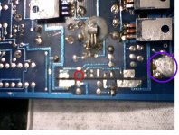
I might have a problem, but need confirmation from someone that has worked on these amps before. While unsoldering the preamp card, one of the pads came off the main board. After looking at it through a magnifying glass, it appears to be just an extra solder pad to add strength to the card mounting. I do not see any traces leading up to where the pad was located. The pad in question was located inside the Red circle. For orientation we are looking at the bottom side of the main board and, the power connections are to the right. One of the thermistors is stood up for clearance and circled in purple. Thanks in advance.
Rgs, JLH
Attachments
It's better if you repair these cards in place. If you have to remove them for some reason and you have a soldering iron with a variable temperature, use ChipQuik. It will help protect the pads on both boards.
ChipQuik is also good for removing the driver transistors. Most people damage the board trying to remove them.
ChipQuik is also good for removing the driver transistors. Most people damage the board trying to remove them.
it's OK to loose one of those pads as they are there just for extra strength as you say, I have lost a few over the years due to inexperience, but like Perry says, ChipQuik is great but the last piece I bought was only about 8" long and lasted 2 minutes!
is there a supplier that can do it cheap in decent size quantities Perry?
is there a supplier that can do it cheap in decent size quantities Perry?
- Status
- Not open for further replies.
- Home
- General Interest
- Car Audio
- Replacing TL074 opamp in Soundstream CA 3.0