Just finished working on some Dynaco Mk3's and a Tubes4HiFi/Bob Latino ST120 Amp and decided to roll my own copy of a Grommes 260A.
Why the 260A? Seems an interesting amp, and that was good enough. The difference is that I'm going to make this a PCB version vs. Point to Point wiring for the heck of it, and to get some use out of all the software I have sitting collecting dust.
Most all of the schematic is the stock Grommes 260A with a few extra places for parts and circuit changes just in case someone might want to tinker with it a bit if I make some extra boards.
Attached are the 2 schematic sheets and the orig Grommes 260A. That's my jumping in point.
Go easy on me, new to diyAudio 🙂
And great forum!
Sandy
Attachments
Great Project Sandy! I am confused however -- are you using a UL output stage as shown? Or, straight pentode mode? Your amplifier page shows UL operation, while your power supply page still shows the screen regulator in place. The original Grommes 260 was a UL amplifier, where as the A version brought the screen regulator and straight pentode operation into play.
Good luck with your amp!
Dave
Good luck with your amp!
Dave
Dave -
I left the output circuit as configurable, so if you don't want to run the 6L6GC and Pentode circuit you can still easily use it in UL mode by cutting a couple of traces and adding a couple of jumpers and of couse the right transformer. (Might need to adjust some dropping resistors values)
Some of the ideas for flexibility -
That all being said, I would expect other component changes, but that is up to the experimenter to figure out as I'm not quite up to speed yet with the math behind all of this 🙂
My plan was to build it 'stock' then tinker, but if you have any suggestions I am all ears as they say!
I have the stock power transformer specs being made by the nice folks at Edcor to spec with a bit more B+ Current and an off the shelf 4.2K output tranformer and choke.
All of this is to try to fit a monblock into a Hammond 10x12x2 box
I'm way to wound up on Coffee today!
Sandy
I left the output circuit as configurable, so if you don't want to run the 6L6GC and Pentode circuit you can still easily use it in UL mode by cutting a couple of traces and adding a couple of jumpers and of couse the right transformer. (Might need to adjust some dropping resistors values)
Some of the ideas for flexibility -
- Solid State or Tube rectifiers
- High voltage B+ Capable Cap
- Ultra Linear or Pentode
- Regulated Bias or Not
- Regulated (well sorta) 12AU7A/12BH7A supply or not
That all being said, I would expect other component changes, but that is up to the experimenter to figure out as I'm not quite up to speed yet with the math behind all of this 🙂
My plan was to build it 'stock' then tinker, but if you have any suggestions I am all ears as they say!
I have the stock power transformer specs being made by the nice folks at Edcor to spec with a bit more B+ Current and an off the shelf 4.2K output tranformer and choke.
All of this is to try to fit a monblock into a Hammond 10x12x2 box
I'm way to wound up on Coffee today!
Sandy
Hi Sandy -- two quick comments to consider:
1. Delete the antiquated damping control, unless your on a hunt for the specialized control and just want the feature for the nostalgia of it all! (Nah, just dump it!)
2. The HF compensation for stability will surely need adjustment when the time comes. The original OPT was very high quality units with extended HF response. Today's units typically don't have that capability so some adjustment will be needed.
Better inter-mix the decaf!
Dave
Dave -
All of that has already been removed. Too hard to find the parts for that, and don't need any more knobs 😉
All of that has already been removed. Too hard to find the parts for that, and don't need any more knobs 😉
Last edited:
I'd make the provision for a zener string based reference for the optional screen regulator..
Would that be something like a resistor from the HV1 B+ to a resistor (existing 100k in the 6L6 circuit) the screen then a string of Zeners that add up to 320V to Gnd?
Forgoing the correct resistor value, would this be the configuration of the circuit? I'm not at the schematic program or I would draw it up as to how I would 'Guess' it works 😉
Hopefully that's all since I'm guessing I'll be tight on board space.
Sandy
My Grommes A260 ......
Hi all,
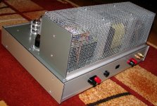
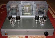
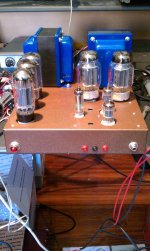
All I can say, is that worth to build, sounds great, and a link Gegentakt-Verstärker in AB-Betrieb für EL34 / 6L6GC ....... I built ,this amp tubes last year with 6P3C Russian output tubes,
and listen to sound almost daily and becoming better.I decided to build it again this superb amplifier with GU50 as finals output tubes. Here are some pictures 🙂
Regards Alex.
Hi all,
All I can say, is that worth to build, sounds great, and a link Gegentakt-Verstärker in AB-Betrieb für EL34 / 6L6GC ....... I built ,this amp tubes last year with 6P3C Russian output tubes,
and listen to sound almost daily and becoming better.I decided to build it again this superb amplifier with GU50 as finals output tubes. Here are some pictures 🙂
Regards Alex.
Attachments
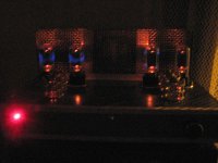
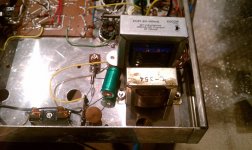
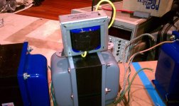
Testing amplifier .....
the image and sound here .....Testing Grommes 260A amplifier - YouTube 😀
Alex.
the image and sound here .....Testing Grommes 260A amplifier - YouTube 😀
Alex.
Sandy -- simply replace the existing 220K 2 watt resistor at the control grid of the 6L6 with an appropriate zener string, and bypass it with at least a .01 uF cap. If you go bigger in capacitance, the circuit will actually provide filtering for the voltage at the output of the regulator, which is always a good thing. A 20 uF cap would be a good value, in addition to the smaller bypass cap. Remember too that you're dealing with a vacuum tube pass element here, so the zener string will likely need to be made up to equal about 310 volts, so that after the tube biases itself, the output at the cathode will be about 320 vdc.
Dave
Dave
Thanks, Alex for the pics, very nice work and good to hear that the amps sound good!
Dave, that seems easy to add, I'll add that to the schematic and hopefully it will all fit on the board. I'll upadate it in the next couple of days when I can get back to the garage for more work. Looks like I can make the string with 3 5w zeners (100-100-110), so might fit fine.
Sandy
Dave, that seems easy to add, I'll add that to the schematic and hopefully it will all fit on the board. I'll upadate it in the next couple of days when I can get back to the garage for more work. Looks like I can make the string with 3 5w zeners (100-100-110), so might fit fine.
Sandy
Getting a bit closer to a final set of schematics. Any last thoughts would be most appreciated!
Minor changes to include transformers in schematic, optional Zener diode for screen regulator on 6L6 and a bit of other schematic clean up.
Thanks!
Sandy
Minor changes to include transformers in schematic, optional Zener diode for screen regulator on 6L6 and a bit of other schematic clean up.
Thanks!
Sandy
Attachments
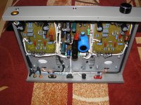
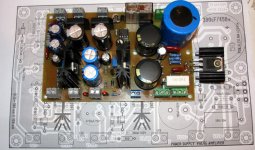
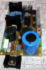
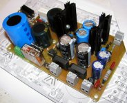
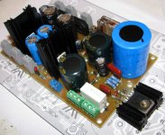
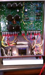
.....schematic of PSU it's complicated for me , 4 valve and many parts included ...... but it's your option 😉 . I already built my PSU and show like in pictures below .
Regards Alex.
Regards Alex.
Attachments
Alex -
I saw you excellent design, and do like your design, but I'm trying to keep things closer to the old design, tube style. I think the only thing that is a bit harder to get is the OB2 regulator, and I picked up a box of 10 for about $25 bucks.
I was originally going to try to do what you did with individual PCB's but figured I would make this really easy to build and am going to do a single board version with the PS and Amp together. While not possibly the best design, should be still very good.
I have to start working on the PCB parts library (for the schematic) since my high tech PCB system does not favor tube/analog parts, then lay out the board. Hopefully the power transformers will show up right around when the PCB is done.
Sandy
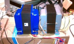
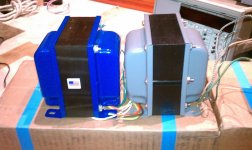
A boat load of Iron has arrived. Very fast from Edcor, what seems like a little under 3 weeks with shipping.
What did I get -
Output transformer - Edcor CXPP100-MS-4.2K 100 Watt 4.2K Pri, Screen taps at 40% (not used in the EZ260's case)
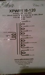
Power Transformer - Edcor XPWR198-120 Matching Grommes 260A specs. I'm not sure if this was a custom version or not, matches the Grommes odd bias and 6A 5v for the dual regulators. Cost was about $92 each (I got 4) so they may have waived the custom fees or it was one that was already in their design books.
Choke Edcor - XC87-2H-350mA
The Output transformer has about a 2.125" thick core and is very similar in size as the Dynaco MKIII Output transformer.
The Power Transformer is the same size core, 2.125" and is definitely has a thicker core then the Dynaco MKIII power transformer which has a 1.625" thick core. So this should be better even with the draw of the extra rectifier tube and related.
Pictures - Outputs (Edcor/Dynaco MkIII), Power(Edcor/Dynaco MkIII), Choke, Power Trans Wiring
What did I get -
Output transformer - Edcor CXPP100-MS-4.2K 100 Watt 4.2K Pri, Screen taps at 40% (not used in the EZ260's case)
Power Transformer - Edcor XPWR198-120 Matching Grommes 260A specs. I'm not sure if this was a custom version or not, matches the Grommes odd bias and 6A 5v for the dual regulators. Cost was about $92 each (I got 4) so they may have waived the custom fees or it was one that was already in their design books.
Choke Edcor - XC87-2H-350mA
The Output transformer has about a 2.125" thick core and is very similar in size as the Dynaco MKIII Output transformer.
The Power Transformer is the same size core, 2.125" and is definitely has a thicker core then the Dynaco MKIII power transformer which has a 1.625" thick core. So this should be better even with the draw of the extra rectifier tube and related.
Pictures - Outputs (Edcor/Dynaco MkIII), Power(Edcor/Dynaco MkIII), Choke, Power Trans Wiring
Attachments
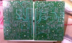
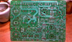
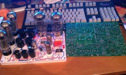
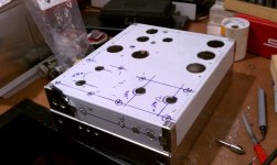
Finally made some progress on the EZ260A Project.
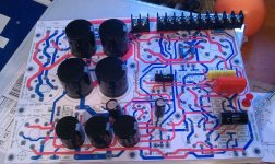
I 'prototyped' the part fitment on foam core to see if the parts would fit and general layout visuals. Basically printed a 1:1 print of the copper and spray glued to foam core. Makes for good parts fitment as you can press through the paper into the foam core and parts hold. Even tube sockets with tubes. Looks cool too 😉
PCB's are from Advanced Circuits, 2oz copper, 0.093" thick, 2 sided silk screen and masks
Here are some pics...
Attachments

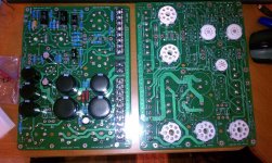
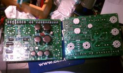
Ok a bit more progress on the EZ260 project. Got the amp sorted out. Built up a couple of the PCB's and took the prototype chassis a part to make the second chassis as I was too lazy to make a fresh pair.
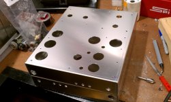
I printed out the mechanical layers of the PCB in 1:1 to make a template for the mounting and tube holes. Center punched everything and began drilling...
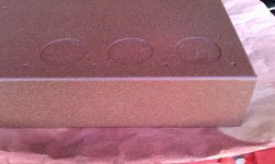
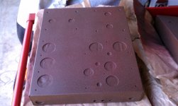
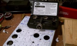
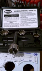
I Used the fantastic Blair Rotobroach tools for the larger holes, smaller were the Irwin Unibit (very clean holes too) and began the paint after masking the underside with magical 'Blue Tape'.
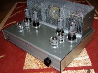
In the vain of Dynaco brown (which I like) I tried some brown primer coated with some outdoor bronze/brown furniture texture paint. It has a very fine texture and I will either coat it with a clear or hit it with a brown to make it more of a texture. Overall I like the looks, but don't want the looks of it to be louder then the sound of the amp.
Pictures attached!
I printed out the mechanical layers of the PCB in 1:1 to make a template for the mounting and tube holes. Center punched everything and began drilling...
I Used the fantastic Blair Rotobroach tools for the larger holes, smaller were the Irwin Unibit (very clean holes too) and began the paint after masking the underside with magical 'Blue Tape'.
In the vain of Dynaco brown (which I like) I tried some brown primer coated with some outdoor bronze/brown furniture texture paint. It has a very fine texture and I will either coat it with a clear or hit it with a brown to make it more of a texture. Overall I like the looks, but don't want the looks of it to be louder then the sound of the amp.
Pictures attached!
Attachments
-
 IMAG1121.jpg277.1 KB · Views: 99
 -
 IMAG1120.jpg196.4 KB · Views: 102
 -
 IMAG1101.jpg203.4 KB · Views: 96
 -
 IMAG1100.jpg173.4 KB · Views: 111
 -
 IMAG1099.jpg211.3 KB · Views: 105
 -
 IMAG1098.jpg350.1 KB · Views: 118
 -
 IMAG1097.jpg225.6 KB · Views: 141
 -
 IMAG1083.jpg353.8 KB · Views: 133
 -
 IMAG1081.jpg255.1 KB · Views: 147
Made a bit of progress getting one of the amps together today. Other one is delayed as I'm missing a couple of mechanical parts to mount the PCB to the chassis. The first amp actually went together very easy and wiring was pretty simple given the layout. The red pilot lamp comes on when powered up...Victory!
Sandy
Sandy
Attachments
- Status
- Not open for further replies.
- Home
- Amplifiers
- Tubes / Valves
- EZ260A Grommes 260A Project