Also note his suggestions only apply to linear unregulated PSU, if using a transformer with a few volts headroom and regulation, capacitance benefits disappear before 1000uF per load amp with the exception of (usually) increasing ESR. However, the extra wire or traces to implement more capacitance can increase ESR more than the difference from the capacitors themselves.
What was your current load?
I hadn't measured the exact load, but it would have been rather minimal (schematic attached).
The history of the capacitance after the bridge rectifiers:
Schematic; 9v: 470uF, 9v: 470uF, 9v (for filament): 10uF, 220v: 220uF.
Shipped with pcb: 9v: 2200uF, 9v: 2200uF, 9v: 2200uF, 220v: 150uF.
Soldered by me: 9v: 22000uF, 9v: 22000uF, 9v: 22000uF, 220v: 470uF.
I have noticed no effects (bad or good) on the SQ from increasing the capacitance to this level. Although admittedly based on the assumption that 'more is better', I had the capacitors laying around and thought I'd use them seeing as the traces were already on the pcb for the larger caps. Is it really worthwhile desoldering to reduce the capacitance to test for the sound upon reducing the capacitance to 220uF per rail?
Attachments
^ Since it doesn't need 22000uF, I would remove those so you have them available for something higher powered and use the 2200uF because you already have them, assuming they are decent quality caps... but 220uF would do the job, the regulation circuit gives you a large range of capacitance you should be able to use with no ill effect. With an oversized -9|0|+9 transformer, you have even more voltage margin, I'd expect those capacitors right after the rectifier bridge stay > 11.0VDC
Last edited:
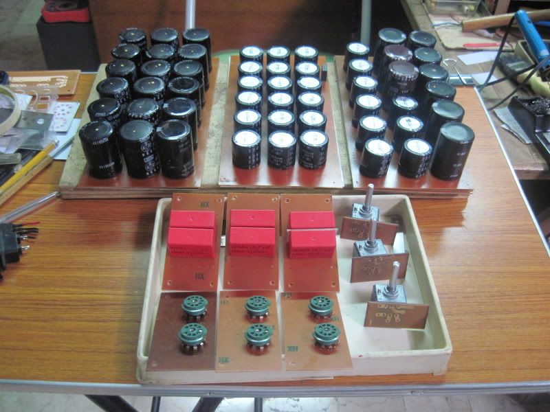
i have been commissioned to build a tube pre-amp, the owner wants multiple caps in the power supply, where just 2 will give excellent results, the owners wants 18caps in the psu:
traffos and chokes:
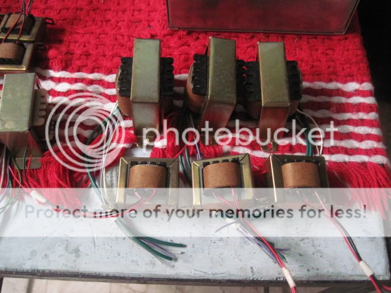
traffos and chokes:
Now *that* appears to seriously be ridiculous!
How are you going to calculate the size of a transformer necessary for this job?
On the back of seeing photos like that, I might leave my 22,000uF in...applying the heat necessary to get the caps off might damage the traces on the board...
How are you going to calculate the size of a transformer necessary for this job?
On the back of seeing photos like that, I might leave my 22,000uF in...applying the heat necessary to get the caps off might damage the traces on the board...
it's not as bad as you may think.....
and i do agree, absolutely ridiculous, but what can i do, it's their money, not mine....😀
and i do agree, absolutely ridiculous, but what can i do, it's their money, not mine....😀
Can you charge them a little more for some film caps to bypass each one of those electrolytics? It will help with inductance (I recall seeing this in a Nelson Pass article somewhere, but have not got around to doing it to my DAC as yet...).
i will, bu i will put those bypass caps right on the board, where they will be of better use....
He is unlikely to be able to hear 18 caps, so will he be satisfied with just seeing them? Use 2, and leave 16 present but unconnected? Then smile when he tells his friends how wonderful it is to have 18 caps in his PSU!
He won't need a transformer.How are you going to calculate the size of a transformer necessary for this job?
Just charge/jump it from a truck 24V battery and then let it run "wireless" for the next month !
We have no idea what his specification is or his listening habits etc.
Not fair to apply "ridiculous" when you are ill informed.
Not fair to apply "ridiculous" when you are ill informed.
Yes - true, however in the context of having freshly discovered that my 22,000uF per rail was ill-informed, forgive my haste to label it as 'appearing' to be ridiculous!!
Last edited:
calculate the continuous current draw of the circuits downstream of the PSU.How are you going to calculate the size of a transformer necessary for this job?
Multiply that continuous by 4.
Select a transformer of suitable voltage with a current rating matching or slightly exceeding that 4 times ratio.
eg.
the pre-amp draws 20mA the Dac draws 50ma, the relay draws (when on) 12mA. The voltage regulators (2 of them) draw 10mA to operate.
The total current draw is 102mA.
The transformer should be a 12Vac, 400mA for a 12V circuit, i.e. >=4.8VA
This is not difficult. It is simple arithmetic. Do the research, invest in your hobby.
Last edited:
contiuous ...... It is simple arithmetic. Do the research, invest in your hobby.
Interesting...I thought I was doing research by referencing articles by Rod Elliott and Nelson Pass, forgive me if everything doesn't come naturally and requires some assistance.
As for your lexical inadequacies...perhaps take the time to do a spelling (or typing) course prior to killing an enjoyable thread.
Sorry I missed that one.
I always proof read before posting and again after posting.
But sometimes a mistake leaks through.
BTW,
I am not prepared to invest the time in a typing course.
I am at the wrong end of my life to start learning touch typing. And probably never acquire the skills of any typist.
I always proof read before posting and again after posting.
But sometimes a mistake leaks through.
BTW,
I am not prepared to invest the time in a typing course.
I am at the wrong end of my life to start learning touch typing. And probably never acquire the skills of any typist.
Last edited:
No worries. Andrew - we all look up to you here at DIYAUDIO and many of us read your posts for insight due to your experience and concise descriptions. Many future readers of this thread will appreciate your example of how to calculate required transformer specs based on continuous current draw! That said, hopefully the thread can now get back on track.
to whom should i build preamps?
if the client asks for more caps, is it to my beneifit to tell him in the face that he is ill informed?
if the client asks for more caps, is it to my beneifit to tell him in the face that he is ill informed?
He is unlikely to be able to hear 18 caps, so will he be satisfied with just seeing them? Use 2, and leave 16 present but unconnected? Then smile when he tells his friends how wonderful it is to have 18 caps in his PSU!
the thought crossed my mind, however i do as i am paid......
the topology is not a straight 18 caps in parallel....
after the FWB rectifier are 2 caps, (2 x 470ufd), to which a common mode choke feeding 12 x 470ufd caps is hooked up, negative ground point is taken after the common mode negative lead, then there are 2 in4007 diodes connecting to 2 sets of 2 x 470ufd, one each channel....
B+ at around 140volts.....
to whom should i build preamps?
To customers, of course. Not people on some internet forum 😀
if the client asks for more caps, is it to my beneifit to tell him in the face that he is ill informed?
Yes, most definitely. But not 'tell him in the face' as that sounds a bit too rude and he might run off. Explaining patiently with examples (stories) for why his view is mistaken is the essence of marketing. Peter Drucker said that 'The purpose of business is to create a customer'. Education is a means of customer creation.
^ or tell the customer there is a new cutting edge design where 1 capacitor performs better than 4 replaced in the old design. 😉
While that doesn't seem unreasonable with the small difference in price at these current levels, a little under 2X factor is usually sufficient so long as it isn't an extreme operating condition (encased/enclosed transformer w/o encasement as a condition of the original part current spec OR very high ambient temperature), "unless" the circuit also has peak currents significantly higher than continuous current.
calculate the continuous current draw of the circuits downstream of the PSU.
Multiply that continuous by 4.
Select a transformer of suitable voltage with a current rating matching or slightly exceeding that 4 times ratio.
This is not difficult. It is simple arithmetic. Do the research, invest in your hobby.
While that doesn't seem unreasonable with the small difference in price at these current levels, a little under 2X factor is usually sufficient so long as it isn't an extreme operating condition (encased/enclosed transformer w/o encasement as a condition of the original part current spec OR very high ambient temperature), "unless" the circuit also has peak currents significantly higher than continuous current.
Last edited:
haha - you could use my story as an example - I have just spent the last 48 hours listening to a dac that I had re-capped in 5 minutes for $40 USD, the capacitance per rail went from 2,200uF to 22,000uF. The result, no difference in sound whatsoever - and I'm down $40! [In fact, I'm more worried about high frequency pulses....but can't hear anything so will leave it as it is instead of wasting electricity to re-solder again!!]
- Status
- Not open for further replies.
- Home
- Amplifiers
- Power Supplies
- Transformers with multiple secondaries - calculaing VA rating