The Class-A Amplifier Site - JLH Class-AB Amplifier
I'm wondering what happened to the c/o distortion, probably its buried by
the 2nd harmonic stuff. Adding feedback as Self shows will make the c/o
distortion far more prominent in the residual for the closed loop case.
Hi,
Must admit it seems a very simple circuit, ideal for active mid/treble with
a film capacitor at the output. Possibly the biasing arrangement could be
improved to allow the reduction of the Re values. Only 5 transistors ....
rgds, sreten.
(Without overall n.f.b. the distortion at full output power
is a little less than 4%, almost entirely second harmonic......
I'm wondering what happened to the c/o distortion, probably its buried by
the 2nd harmonic stuff. Adding feedback as Self shows will make the c/o
distortion far more prominent in the residual for the closed loop case.
Hi,
Must admit it seems a very simple circuit, ideal for active mid/treble with
a film capacitor at the output. Possibly the biasing arrangement could be
improved to allow the reduction of the Re values. Only 5 transistors ....
rgds, sreten.
Would you like to share the source of this definition; Is it not in error using Douglas Self's redefinitions, as it seems? I think in any case you'll find the transition is from class A to AB whilst B (unbiased) is never used in traditional audio amplifiers or terminology since germanium days. Self's redefined class B is a condition where only optimal bias is used. That's proper AB in forum terms, as I read them.
Otherwise, we can't tell what you're agreeing about. 😕
Hi,
Its pointless arguing the correct definition, the ambiguity is always
going to be there, as is the ambiguity of what is "optimum" bias.
A typical arrangement is 1/4 A, biased to half the current for full A.
This is class AB for certain, and has nothing to do with optimum bias.
(Why I'd prefer class aB to denote minimal required class B biasing.)
For push-pull even full A is AB, because A is defined for a given load,
and on encountering a lower load at full power "full" A goes into B.
Having said that, non push pull class A will simply clip, not do B.
There is no contradiction in Self's scheme - but I don't like it.
I cannot understand how you can find BJ's summary confusing. 😕
rgds, sreten.
Last edited:
Would you like to share the source of this definition; Is it not in error using Douglas Self's redefinitions, as it seems? I think in any case you'll find the transition is from class A to AB whilst B (unbiased) is never used in traditional audio amplifiers or terminology since germanium days. Self's redefined class B is a condition where only optimal bias is used. That's proper AB in forum terms, as I read them.
Otherwise, we can't tell what you're agreeing about. 😕
We are almost there
I really do not know what "proper AB in forum terms" really means other than that all of the many forum members may undertsand different things. I only know electronic engineering terms.
Let me try again.
Class A......Over the whole operating power range of current and voltage into a load impedance ( a speaker ) both halves of the output stage will be continually in conductance so that there is no change in transfer characteristic or "crossover".
Class B...... Only one half of the output stage conducts at any time, EXCEPT that to ensure that one or other half is always conducting a small amount of bias is applied and is usually designed so as to minimise the step change in the transfer characteristic. ie. to minimise crossover distortion. This is technically speaking, in the strictest sense, class AB but only minimally so and in the modern era is simply referred as class B
Class AB..... The amplifier is designed with a very high level of bias current so that significant output power is generated entirely in class A and only at high power does one half device switch off over a proportion of a signal cycle. There is no attempt made to optimise the bias so as to minimise crossover and it is accepted that at such higher power there will be a step in the transfer characteristic.
The JLLH design I referred to in an earlier post was published by Wireless World in June and July 1970 and a copy can be found here :-
The Class-A Amplifier Site - JLH Class-AB Amplifier
I modified this to even higher bias currents ( as I explained earlier ) and when used with high impedance speakers eg. Quad ESL57's of (say) greater than 8 or 10R then operation over the whole power range is in class A. Only when lower impedance speakers are used (say) less than 8R does high power cause operation to move into the class B region at all. I might add that there is a dip in the impedance of an ESL57 at high frequency ( as there are at various frequencies in all loudspeakers ) that could cause a move into the class B region but is unlikely to do so because there is very little energy in a typical audio signal at those high frequencies.
You might also look up a design for a 15/20W amplifier in the Mullard Transistor Audio and Radio Circuits handbook 2nd ed. from 1972. Into 8R it operates entirely in class A to a maximum of 15W and into 4R it produces 20W in class AB.
Have I clarified or confused further?
Last edited:
Hi,
FWIW my original post is about the inevitable step in the transfer characteristic
for high bias AB, and the best approach to ameliorate any detrimental effects.
The JLH design is interesting, but the step will be severe, relatively speaking.
rgds, sreten.
I agree the ESL57's are perfect for a low current class A amplifier, well
over most of the range. Vicious dip right at the top end, which suggests
that push-pull class A(B) is the only sensible version of class A to use.
Means that a high bias JLH AB seems a better choice than the JHL A.
Last edited:
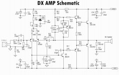
DXamp schematic
The DXamp schematic, high bias AB is very easy,
TBH it seems almost perfect for simple high bias AB.
(For the reasons outlined in the first post.)
rgds, sreten.
(Some compensation issues though, I'm investigating 2 pole.)
Very cheap kits available fron ebay.
The DXamp schematic, high bias AB is very easy,
TBH it seems almost perfect for simple high bias AB.
(For the reasons outlined in the first post.)
rgds, sreten.
(Some compensation issues though, I'm investigating 2 pole.)
Very cheap kits available fron ebay.
Attachments
Last edited:
Hi,
more exactly:
In class B the devices conduct 50% of the cycle and are both shut off when no signal is present.
In class AB the devices conduct more than 50% but less than 100% of the cycle, the operating point is usually near the cut-off region.
In class A the devices conduct 100% of the cycle, crossover distortion does occur, but no switching distortion.
As a conclusion, to avoid the obnoxious switching distortion, set the bias point as high as you can.
Hi,
more exactly:
a)In class B the devices conduct 50% of the cycle and are both shut off when no signal is present.
b)In class AB the devices conduct more than 50% but less than 100% of the cycle, the operating point is usually near the cut-off region.
c)In class A the devices conduct 100% of the cycle, crossover distortion does occur, but no switching distortion.
As a conclusion, to avoid the obnoxious switching distortion, set the bias point as high as you can.
Hi,
a) is impossible.
b) is half right / wrong, except for what Self calls class B.
c) is nonsense.
rgds, sreten.
High bias class AB is what this thread is about, is it not obvious ?
Last edited:
Hi,
a) is impossible.
b) is half right / wrong.
c) is nonsense.
rgds, sreten.
He s right , provided you understood his meanings..
a) EACH device conduct 50% of the time, both being switched off
in the zero volt output condition.
And so on for the two other cases..
Of course, he use a symetric signal, in respect of time, for his exemple
such that the duty cycle is 50% for each device..
High bias class AB is what this thread is about, is it not it obvious ?
With BJTs , contrary to lateral fets , a high bias will provide
few advantages and can even be counterproductive.
BJTs have an optimum biaising depending of the devices caracteristics,
but it s always at a relatively low value between 50 to 80mA in most cases.
Increasing the biaising current over this value will inevitably degrade
the distorsion performance...
Hi,
This thread is not remotely about optimum biasing of a push pull output
stage that is not class A, so its some form of AB or in my terms aB.
Read the whole thread. It has nothing to do with class B optimum bias.
rgds, sreten.
sreten, could you come up with a carefully considered explanation, please.
Hi,
Being smart is all about asking the right questions, and in this
case your not asking me what I should carefully consider.
e.g. - both devices are on 50% of the time. Both are off at 0.
Your numbers don't add up as 50% on + 50% on = 100% on.
Your defining an impossible point at zero, it does not exist.
rgds, sreten.
Given the above the obvious question is what happens at zero.
Last edited:
Crossover distortion doesnt appear at around zero volts in my experience.
The distortion in the waveform comes nearer 90 degrees amd 270 degrees.
I guess thats when the transistors are starting to turn off and the back EMF from the speaker feeds back into the amplifier.
The distortion in the waveform comes nearer 90 degrees amd 270 degrees.
I guess thats when the transistors are starting to turn off and the back EMF from the speaker feeds back into the amplifier.
Crossover distortion doesnt appear at around zero volts in my experience.
The distortion in the waveform comes nearer 90 degrees amd 270 degrees.
I guess thats when the transistors are starting to turn off and the back EMF
from the speaker feeds back into the amplifier.
Hi,
This thread is categorically nothing to do with c/o distortion, seems
I made a mistake in what people understand to be proper class AB.
Though it might be true, its irrelevant in this context.
rgds, sreten,
Last edited:
From what I recall for something to be considered truly class B, each half of the output stage must only conduct for say 50% of the time, if we're considering a sine wave for example.
The trouble comes when the amplifier is asked to drive a reactive load, where the negative side of the amplifier could be asked to deliver current during a positive voltage excursion. This as far as I have been lead to believe violates class B definitions.
I think this was the reason why the term 'optimally biased class AB' is preferred. With anything else being over biased class AB.
For the sake of argument however isn't calling a product class A a bit of a misnomer? Any over biased class AB amplifier could be considered class A, providing it's region of class A operation isn't exceeded. And to my knowledge most coined class A amplifiers will leave class A operation at some point during certain conditions. So really they should be called over biased class AB.
One thing I have never understood is the 'class A' amp with one pair of high power output transistors. These are usually powered from ~25 volt rails and will give something like 20 watts of class A into an 8 ohm load. They will drive 4 ohm loads, but will leave the class A region when doing so.
Why power the amplifier from only 25 volts? It has the required heat-sinking to support an optimally biased class AB amplifier. Why not run the thing off 40 volts and then bias it so that you get the same 20 watts of class A into 8 ohms. Now at least you've got some additional head room to play with and certainly leaving the class A region of an over biased class AB amplifier should be preferable to clipping the amp run on 25 volts.

I cannot agree your restricted ClassAB definition.I do think we have wandered off due to misunderstanding and confusion between proper class AB and the marginal AB biasing required for satisfactory operation of class B. If I may restate...
In a class AB amplifier ( a proper one ) the standing bias current is at a relatively high level. .............................
As such it is a technique only appropriate to domestic amplifiers of say 10 to 30 watts power.
ClassB and 50% duty cycle is the correct definition.
It may be impractical/impossible to exactly hit that 50%, but that is the definition.
It is a pity that D.Self muddied the waters but he was careful enough to actually define "his ClassB" so that others can see how it meets with their interpretation. I have no problem with that. One can call it what one likes provided one defines so that all other can understand.
ClassAB has a standing (bias) current where both devices control all the signal that passes to the output. When that signal is increased, one device takes over the whole control of the signal passing to the output. For this definition of ClassAB it does not matter whether the inactive device is passing zero current or 1uA or 100uA. What matters is that the inactive device is not actively controlling the output current during part of the signal cycle.
ClassA is defined as both devices actively controlling the output current over the whole cycle of the waveform and neither side hands over control to the other.
Single ended ClassA is different from Push-Pull ClassA, as already mentioned, in that overloading of single ended ClassA results in current limiting.
Whereas Push-Pull ClassA, when overloaded, can almost seamlessly transition to ClassAB.
Last edited:
The Class-A Amplifier Site - JLH Class-AB Amplifier
I'm wondering what happened to the c/o distortion, probably its buried by
the 2nd harmonic stuff. Adding feedback as Self shows will make the c/o
distortion far more prominent in the residual for the closed loop case.
Hi,
Must admit it seems a very simple circuit, ideal for active mid/treble with
a film capacitor at the output. Possibly the biasing arrangement could be
improved to allow the reduction of the Re values. Only 5 transistors ....
rgds, sreten.
It is a very early design and as a complete design it does have shortcomings of which you have spotted some. The modifications I made over a long period of time partly made use of modern devices and optimisation of various standing currents and component values to increase the open loop gain. This transformed the performance and operating in class A, ie. into higher impedance speakers does not exceed 0.01% up to the clipping point.
Hi,
FWIW my original post is about the inevitable step in the transfer characteristic
for high bias AB, and the best approach to ameliorate any detrimental effects.
The JLH design is interesting, but the step will be severe, relatively speaking.
rgds, sreten.
I agree the ESL57's are perfect for a low current class A amplifier, well
over most of the range. Vicious dip right at the top end, which suggests
that push-pull class A(B) is the only sensible version of class A to use.
Means that a high bias JLH AB seems a better choice than the JHL A.
Exactly, and i don't hold up JLLH's design as a paragon, it is just the one I have worked with, and which uses less circuitry in total than most output protection circuits.
I think there are only two ways taht the step in the transfer function can be ameliorated...
a.) by biasing the point to an adequately high power that it is in practical terms un-noticeable, and.
b.) designing in enough open loop gain over a broad frequency characteristic to minimise it.
- Status
- Not open for further replies.
- Home
- Amplifiers
- Solid State
- Class AB is being mismaligned ?