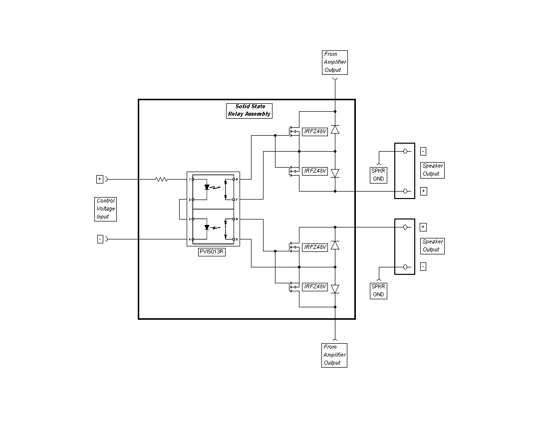
Here's what I use - simple, reliable, easily scalable, and quiet.
This is a nice idea.
I am thinking that it would also be possible to put these devices in the speaker ground return so the switching to the gates would be ground referenced. You would not be able to close the feedback loop around the MOSFET switches as you can do easily in your implementation, but at a few mOhms, that would hardly be a concern anyway. My only issue with the ground based scheme would be how it would handle the inductive kickback as the switches opened. Might need a snubber of some sort across the mosfets.
Just to look at this from another angle...
is there any information on just what is "survivable" by a loudspeaker ? Although a lot of effort goes into DC protection... and to incorporate many of the ideas in this thread could easily make a protection circuit more complex than the amp its protecting... is it actually going to work ?
It could be instructive to develop a heavy duty PWM switch fed from a normal power amp PSU and connect some old speakers up and actually pulse them with DC. 1ms, 2ms etc until something goes pop.
It's the DC switching spec that is important.
Plus the duration, few relay manufacturers offer such data.
(e.g. the magnetically make/break forced relays i showed handle 350A during 0.1s, or 30A for an hour, within the Weibull 95% reliability specification)
Jacco,
Yes I agree. The panasonic relays I put up can do 10A at 100vDC and 100k cycles. They will also do 30A at 100V, but critically the lifetime is then only 30 switching events. A huge difference.
Molly
My speakers took about 3 sec to destruct. I am sure if I could have disconnected them within 100ms or so they would have survived.
Provided it was done with a latching mechanism, to prevent the pulse being repeated until something goes.
HI Andrew,
Yes the IRF540 will work just fine. If you have four IRF540's, a DPST switch and a couple of resistors (anything from 10K to 1Meg shhould be fine) it's simple to try. Only difference is the Rds rating of the IRF540 is nominal .044 ohms compared to .012 for the IRFZ48V that is shown in the original schematic. So with two of them in series total resistance in output to speakes would be increased by about .088 ohms, not huge, but will very slightly decrease damping factor of the system, that is one of reasons I chose the one I did. There may be newer MOSFET's available now that have even lower Rds at acceptable voltage rating than when I put mine together. And realize that adding such a small resistance to most systems probaly won't be audible at all. Also, the MOSFET's will not dissapate any power to speak of, so heat sinking isn't necessary.
Mike
would irf540 do as an experiment for solid state relay?
Too high Rdson. It will work, however. Search IR parts for SMPS purposes.
Vds rating of Mosfets should be at least +-Ub, and is inevitable to use fast clamping diodes (rated 2A and more) from + Out (behind mosfet switch ) to +Ub,-Ub.
Relays introduces 3th. harmonic distorsion
Hi all
Many years ago I build a lot of amplifiers and in the proto types I never used
relays, but in the finished product used "loudspeaker savers".
Listening test showed the finished product to sound less good.
Measurements clearly showed 3th. harm. after the relay and much less before it.
Some companies have use a work around by splitting the feedback loop taking some before the relay and some after.
Today I would not use relays.
Vitreus.
Is the 3th. harmonic increased after the relay because of the relay contact resistance?
Panasonic relay application guideline recomends Silver Tin Oxide (AgSnO2) as having
superior welding resistance characteristics equal or better than Silver Cadmium Oxide (AgCdO2).
If this is true for DC conditions I can not tell.
Panasonic relay application guideline recomends Silver Tin Oxide (AgSnO2) as having
superior welding resistance characteristics equal or better than Silver Cadmium Oxide (AgCdO2).
If this is true for DC conditions I can not tell.
Last edited:
Relay and 3th. harmonics
Dear Tommy1000
It is because of the unlinear resistance of the relay as a function of current through it, the distortion was like -60dB.
Using relays for input selection also presents a problem, very few relays are specified for use with very small currents.
Using a rotary switch with good contact pressure is much preferred.
Regards
Vitreus.
You used very bad relays...Attached picture is measured behind quite ordinary relay , at 100W/8ohm. Good relay is not a problem in terms of distortion, but in switch-of at high currents and DCIt is because of the unlinear resistance of the relay as a function of current through it, the distortion was like -60dB.
Attachments

Last edited:
Yes, both Self and Cordell discuss this. Some relays have a problem (unfortunately neither author actually quotes part numbers which would have been very helpful) but for the rest they are essentially distortionless.
However, I am looking more and more at using a pair of low Rdson mosfets in the speaker return line i.e 0V for protection and ditching the relay all together. You can get 100V mosfets nowadays with c. 10m Ohm Rdson. And, if they are in the ground line, the gate control should be a cinch.
BTW, I will pick up my bass drivers tomorrow or Thursday.

Agree with Michael Chua, supply rail fuses are the answer. I use miniature soldered in fast acting types. Choose a value that will just blow when the amp is running a continuos sine wave at clipping into the minimum impedance.
Henry
Henry
Auto relays work almost faultlessly in a hostile DC only environment.
You can buy a decent 16A (or higher) contact rating 12V from any auto dealer.
I second that proposition..😉
One can use trucks relays since they are rated for 24V DC contacts,
although they must cost more than cars dedicated ones wich are really
cheap and plethoric.
I use car relays rated for 25/30A CT, but the ultimate move was
to downgrade my mosfet amp s PS down from +-55V to +-20V...
I do not think so. Arc (starting) DC voltage of 75V or 12/24V is a HUGE difference in creating of arcing conditions.
BTW, I worked as a research worker in the field of HV and LV circuit breakers, we analyzed and measured both DC and AC circuit breaking phenomena.
BTW, I worked as a research worker in the field of HV and LV circuit breakers, we analyzed and measured both DC and AC circuit breaking phenomena.
Cars max battery voltage is rated at 15.6V by manufacturers,
trucks are rated at 31.2V max , so it s a safe guess that 24V relays
have some security margin well over 24V for contacts arcing , but with
some restrictions that are up to the relays purpose :
Looking at Werhle s catalog , we can see that 24V/20A CT relays are proposed
in two flavours, one with contacts normally open , and thus non subject to arcing,
and those with contacts that are designed to withstand changes and thus can be
used as normally closed and as such will experiment arcing.
The specification is rated down from 20A to 10A whether the relay is to be used
normally open or closed respectively..
http://www.krautli.ch/fileadmin/download_katalog/WEHRLE_Katalog.pdf
Any arcing damages the contacts, it doesn't matter what they are made of. Once an arc has been drawn the contact is impaired.
If the relay contacts do open successfully and save your speakers then you are fortunate, they probably wouldn't do so a second time.
You can talk about the theory for ever... go and get an old bass speaker and "flash" the terminals across a 12 volt PSU or an S.L.A. battery (relevant safety precautions apply). Now imagine that over 40 or 50 volts or more.
The SS relay has much to commend it.
- Home
- Amplifiers
- Solid State
- Output Relays