Getting some conflicting information from various online calculators. I have a simple peak I'm looking to tame at 630 Hz. It is 6dB strong, and about 3dB strong on either side at 500Hz and 800Hz respectively. Beyond that it is basically flat.
I'd love to come up with some consistant inductor, capacitor and resistor values as a starting point. Can anyone help?
Thanks 🙂
I'd love to come up with some consistant inductor, capacitor and resistor values as a starting point. Can anyone help?
Thanks 🙂
May be it is conflicting because it is not sure which one is parallel and which one is series?
Are you talking about the notch filter which is in parallel with the driver?
Are you talking about the notch filter which is in parallel with the driver?
May be it is conflicting because it is not sure which one is parallel and which one is series?
Are you talking about the notch filter which is in parallel with the driver?
I believe it is called a parallel notch because the three components are connected in parallel. It is however in series with the driver. I think a series notch filter is typically used to tame a resonance around the drivers Fs point. The parallel notch can be designed to tame any peak in a drivers operating range.
I believe it is called a parallel notch because the three components are connected in parallel.
Okay, I understand. I have checked the internet, indeed one site has erroneous calculator. This one attached is okay (but it is theoretical). In practice it is a bit different
Attachments
Last edited:
Thank you! I did see that calculator but was concerned that the formula may have been off. Is there a preference as to whether the notch filter go between the driver and crossover, or crossover and amp?
Is there a preference as to whether the notch filter go between the driver and crossover, or crossover and amp?
It depends on the real crossover: what drivers are affected at 630Hz? If this peak is on total response, and there are more than one driver producing this frequency signal, then you have to put between amp and xover if you expect a theoretical (symmetrical) notch.
In a 3-way, at 630Hz usually 2 drivers are in effect so you cannot put the filter on the woofer or midrange alone.
matevana, you cannot put the filter between the amp and crossover for your needs. The filter requires source impedance to work (something in series before it). Putting a notch filter before the crossover has another purpose and is useful for modifying the impedance to make the speaker easier for the amp to drive, but this is often not done.
This is a simple 2 way design crossed at 2k Hz. Since the peak occurs at 630 Hz, I am assuming its all coming from the woofer rather than the system. I gather then the notch filter should go between the crossover and the woofer?
That should work.
I am wondering where this would be coming from. Have you investigated the possibility of floor bounce?
I am wondering where this would be coming from. Have you investigated the possibility of floor bounce?
That should work.
I am wondering where this would be coming from. Have you investigated the possibility of floor bounce?
Yes... quite possibly. It's also a dipole so rear radiation bouncing from the wall behind them comes into play. The same drivers (usher 8137a) did not exhibit the peak in a box.
I have a similar question. In my case I want to tame that 10db peak at about 1,800 hz that the Alpha 15A has. I figure that would need a 66.73 uf cap, 2.65 ohm resistor and a 1.67 mh inductor. But would it mater if I used a super cheap inductor with an ohm or more resistance ?
Here is a link to a fairly good online calculator for parallel notch filters. Just figure out what frequency is at the peak you want to tame and what the frequencies are on either side of the peak at 3db down enter those numbers into the calculator and hit enter. There are quite a few different calculators on this site that can be used for a text book starting point when customizing a x-over. I have had good luck with them.
Parallel Notch Filter Designer / Calculator
Parallel Notch Filter Designer / Calculator
Last edited:
It may be OK. The resistance is wanted in this circuit, and in this case it won't likely dissipate much power.
I prefer calculators that also ask for the speaker Re like this one: Calculate Parallel Notch Filtern. The calculator will generally just get you in the ballpark. Remeasuring and tweaking the values will most likely be necessary.
These calculators are a bit rough and ready in practice. They don't tell you anything about the circuit around a woofer or its inductance. I think they usually assume a flat impedance driver, which the Alpha 15A certainly isn't.
ALPHA-15A - Loudspeakers | Eminence Speaker
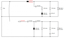
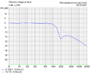
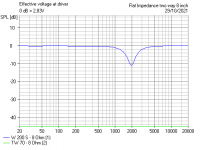
I am seeing horrible 2kHz resonance there, and the impedance curve corroborates this. Very rough and ready on a woofer of similar inductance and resistance, but a proper sim with impedance correction throws up something like this for a series LCR, which is less interactive IMO.
I always remember that 5uF and 0.2mH series LCR is 5kHz. So multiply accordingly for 2kHz, by 2.5. Then adjust for the Q. This looks reasonable. It's horrible without impedance correction. The 1mH coil size is very affecting of the overall slopes. Might help a bit. Could probably do this for a parallel LCR, but only if you are interested.
ALPHA-15A - Loudspeakers | Eminence Speaker
I am seeing horrible 2kHz resonance there, and the impedance curve corroborates this. Very rough and ready on a woofer of similar inductance and resistance, but a proper sim with impedance correction throws up something like this for a series LCR, which is less interactive IMO.
I always remember that 5uF and 0.2mH series LCR is 5kHz. So multiply accordingly for 2kHz, by 2.5. Then adjust for the Q. This looks reasonable. It's horrible without impedance correction. The 1mH coil size is very affecting of the overall slopes. Might help a bit. Could probably do this for a parallel LCR, but only if you are interested.
Attachments
It gets worse! 😕
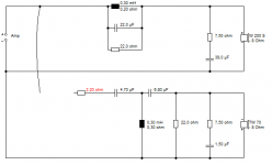
I just looked at a parallel notch. I didn't get anything REMOTELY like Woody's values! 😕
And it went completely haywire when adding a bass coil or losing the impedance correction. I think I'll go to bed. 😀
I just looked at a parallel notch. I didn't get anything REMOTELY like Woody's values! 😕
And it went completely haywire when adding a bass coil or losing the impedance correction. I think I'll go to bed. 😀
Attachments
- Home
- Loudspeakers
- Multi-Way
- Help with parallel notch filter