Bill
Measured across the 221 ohm resistors attached to the gate of the output fets and all measure a couple of mV (If that) but one measures 2.6v.
could that be the problem-?
dare i replace it?
G
Measured across the 221 ohm resistors attached to the gate of the output fets and all measure a couple of mV (If that) but one measures 2.6v.
could that be the problem-?
dare i replace it?
G
If you trust your measurements, that fet is shot. That's one of the bottom ones I would bet.
If you know how to test them, pull it out and test it.
Best, Bill
If you know how to test them, pull it out and test it.
Best, Bill
Thanks Nelson
thanks for your rather unambiguous statement- i need that sort of direction..
many thanks to all those who have assisted thus far , hopefully I will, be able to resolve the problem tonight...
Regards from downunder
thanks for your rather unambiguous statement- i need that sort of direction..
many thanks to all those who have assisted thus far , hopefully I will, be able to resolve the problem tonight...
Regards from downunder
Remember that all the FETs in the bottom leg are "MATCHED"
You cannot just replace one without matching the devices.
I have some spare matched IRFP244s which have been listed under SWAP-MEET.
You cannot just replace one without matching the devices.
I have some spare matched IRFP244s which have been listed under SWAP-MEET.
Thanks for the offer Andy ,
sadly my unit uses the irf240's....not sure if the 244's would causes issues...?
Cheers
sadly my unit uses the irf240's....not sure if the 244's would causes issues...?
Cheers
I managed to get 4 x 6 matched pairs out of a batch of 50.
Statistically you might need to buy 12 of them to get a set of 6 closely matched.
Statistically you might need to buy 12 of them to get a set of 6 closely matched.
Hi Andy
How much for postage to the land downunder?
say 6 matched pairs?
cheers
I'm still talking about IRFP244s here, is that what you are after ?
Apologies , Voltage acroos the source resistors is only a few mV not 1.6V.....
I'll keep looking
Thanks guys
I'll keep looking
Thanks guys
George, I assume you mean the gate resistors.
If so, then you need to figure out what's holding the bottom fets fully on. What is the bottom gate to minus rail voltage, it should be around 4.5V.
If so, then you need to figure out what's holding the bottom fets fully on. What is the bottom gate to minus rail voltage, it should be around 4.5V.
Hi Andy
Under a worst case scenario i would consider 244's as part of a complete rebuild if required.
I already have about a dozen 244's (untested as yet ) and 6 of 240's from the original build- but the recorded values on the fets has faded - so need to retest
Cheers
Under a worst case scenario i would consider 244's as part of a complete rebuild if required.
I already have about a dozen 244's (untested as yet ) and 6 of 240's from the original build- but the recorded values on the fets has faded - so need to retest
Cheers
ok now it gets really screwwy
bottom gates to neg rail is negative 32V on bad channel
bottom gates to neg rail is negative 32v on GOOD channel (yes it works) 50mv offset
top gates on bad channel positive 32 v
Top gates on GOOD channel positive 4.5v
have I an earthing or wiring problem?
bottom gates to neg rail is negative 32V on bad channel
bottom gates to neg rail is negative 32v on GOOD channel (yes it works) 50mv offset
top gates on bad channel positive 32 v
Top gates on GOOD channel positive 4.5v
have I an earthing or wiring problem?
George, that's why I originally asked if you trusted your measurements, it's very easy to get confused when poking around.
On the top measurements, can you be more specific about where you are measuring. The reading should be from the output or source resistor to the gate and should be somewhere in the 4V range.
On the top measurements, can you be more specific about where you are measuring. The reading should be from the output or source resistor to the gate and should be somewhere in the 4V range.
After reading your post again, if your measurements are correct, neither channel would be working. Top AND bottom gate to source readings should all be in the 4V range.
Hi Bill
yes i was wrong (am tired 1/2 hr sleep in 2 days - abt to go to bed)
neg rail to bottom gates 27mv, 2.6v , 2.6v 9 off fets per rail
thanks heaps for your efforts
yes i was wrong (am tired 1/2 hr sleep in 2 days - abt to go to bed)
neg rail to bottom gates 27mv, 2.6v , 2.6v 9 off fets per rail
thanks heaps for your efforts
For a short term test you can simply remove the faulty FET.
The others will get rather HOT rather quickly but it would prove the point.
As you are running on reduced power rails from the Aleph 4s +/- 48V you should have no problems.
Similarly. If the MOS-FETs are easy to get to, why not use the amp itself to see if any of your spares are a good enough match for those that are still working.
Fit one at a time and compare the voltage across the source resistors on that leg. +/- 1-2% is an excellent match. It'll be tedious and time consuming but very rewarding in the end.
sorry 3 fets per rail - fat fingers typing
That's not an Aleph 4 clone.
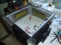
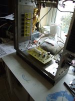
My Aleph 4 has got 6 FETs per leg, 24 in total.
Attachments
- Status
- Not open for further replies.
- Home
- Amplifiers
- Pass Labs
- Aleph 5 help please-32v at output