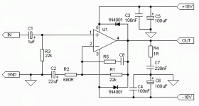
Ok in the image of the schematic has 100nF i read and they said that is also
0.1µF or is it 0.10µF and also the 220nF is it 0.22µF i just want to clarify that if is true.
And the R4 is it a 1ohm resistor, and the potentiometer is it a 22K...
The other question i have could this be power with two 9V battery.
Well thank you...")
0.1µF or is it 0.10µF and also the 220nF is it 0.22µF i just want to clarify that if is true.
And the R4 is it a 1ohm resistor, and the potentiometer is it a 22K...
The other question i have could this be power with two 9V battery.
Well thank you...
Attachments
Last edited:
Nope . 9 V batteries ,also known as 'transistors battery' because of their particular usage in portable radios ,micro-trasmitters ,remote controls etc. ,
are not made for power duties as a low frequency amplifier is .
A LF amp is a ..modulated power supply and the average power is determined by that important element . Indeed the cost of the PSU is more than half of the total cost of components required for an amplifier ,also in terms of space requirements .
The 'comma' changements are ok : pico ,nano ,micro ,milli .....
are not made for power duties as a low frequency amplifier is .
A LF amp is a ..modulated power supply
and the average power is determined by that important element . Indeed the cost of the PSU is more than half of the total cost of components required for an amplifier ,also in terms of space requirements .The 'comma' changements are ok : pico ,nano ,micro ,milli .....
Nope . 9 V batteries ,also known as 'transistors battery' because of their particular usage in portable radios ,micro-trasmitters ,remote controls etc. ,
are not made for power duties as a low frequency amplifier is .
A LF amp is a ..modulated power supply
The 'comma' changements are ok : pico ,nano ,micro ,milli .....
Ok, Thank you so much for that info, if not a 9V battery, so a adapter 9V but how many Amp or mA...
...maybe you are in the same situation of Chuck55 ,see thread http://www.diyaudio.com/forums/solid-state/189849-15-0-15-supply-c.html
and you require a beefier PSU ,in the 1 A range.
and you require a beefier PSU ,in the 1 A range.
power supply requirements
It´s maybe works, but not well as you want.
Try using a 2A 15-0-15V center tapped transformer for better performance and 2X3300uF for filter cap in power supply.
The other question i have could this be power with two 9V battery.
Well thank you...
It´s maybe works, but not well as you want.
Try using a 2A 15-0-15V center tapped transformer for better performance and 2X3300uF for filter cap in power supply.
after retification and filtration, the 15-0-15 trafo will be producing a bit over +/- 20 volts at idle current. This is over the max supply voltage of the TDA2030.
Unless you have a stock of 2030s, I'd suggest using the TDA2050. It has a better output swing at a given supply voltage and supports a higher Vs and peak current.
You can use two 9 volt batteries, but with lower supply voltage comes much reduced output power and the batteries would not run very long. You would have to use 16 ohm speakers to get just a couple hours of listening. You would be better off using a couple 12v SLA batteries and 4 ohm loads.
It´s maybe works, but not well as you want.
Try using a 2A 15-0-15V center tapped transformer for better performance and 2X3300uF for filter cap in power supply.
OK Thank you for the comment... but im not really understanding the whole
##-0-##V i been seen other post and there recommending those number to other members... but thank you anyways...
after retification and filtration, the 15-0-15 trafo will be producing a bit over +/- 20 volts at idle current. This is over the max supply voltage of the TDA2030.
Unless you have a stock of 2030s, I'd suggest using the TDA2050. It has a better output swing at a given supply voltage and supports a higher Vs and peak current.
You can use two 9 volt batteries, but with lower supply voltage comes much reduced output power and the batteries would not run very long. You would have to use 16 ohm speakers to get just a couple hours of listening. You would be better off using a couple 12v SLA batteries and 4 ohm loads.
Thank you... i just have to ask but how many ohm those a bookshelf have the stereo has 30W output...
thanks again....
1uF = 1000nF = 1000000pF
2F = 2000mF = 2000000uF = 2000000000nF = 2000000000000pF
You can see why we have adopted the "multipliers" to help reduce the risk of errors in the typing of these long strings of digits.
Similarly
47pF = 0.047nF = 0.000047uF = 0.000000047mF = 0.000000000047F
22k for R3 is a fixed resistor. It is not a volume control.
R3 = 22k, sets the input impedance of the amplifier. If you want to use a passive attenuator to drive the input cable to the amplifier, then I would recommend a pot value of ~5k for that Rin=22k.
If you adopt a buffer after the pot, then the pot value can be changed to something much higher, either 50k or 100k.
2F = 2000mF = 2000000uF = 2000000000nF = 2000000000000pF
You can see why we have adopted the "multipliers" to help reduce the risk of errors in the typing of these long strings of digits.
Similarly
47pF = 0.047nF = 0.000047uF = 0.000000047mF = 0.000000000047F
Yes 1r0 = 1ohm.And the R4 is it a 1ohm resistor, and the potentiometer is it a 22K...
22k for R3 is a fixed resistor. It is not a volume control.
R3 = 22k, sets the input impedance of the amplifier. If you want to use a passive attenuator to drive the input cable to the amplifier, then I would recommend a pot value of ~5k for that Rin=22k.
If you adopt a buffer after the pot, then the pot value can be changed to something much higher, either 50k or 100k.
Last edited:
"The other question i have could this be power with two 9V battery.
Well thank you... "
absolutely will work.
in fact, at first startup i would strongly recommend it.
allso, depending on the driven speakers efficiency and how loud you want it to be, it may even be more than enough. it all depends realy on the application.
Well thank you... "
absolutely will work.
in fact, at first startup i would strongly recommend it.
allso, depending on the driven speakers efficiency and how loud you want it to be, it may even be more than enough. it all depends realy on the application.
1uF = 1000nF = 1000000pF
2F = 2000mF = 2000000uF = 2000000000nF = 2000000000000pF
You can see why we have adopted the "multipliers" to help reduce the risk of errors in the typing of these long strings of digits.
Similarly
47pF = 0.047nF = 0.000047uF = 0.000000047mF = 0.000000000047F
Yes 1r0 = 1ohm.
22k for R3 is a fixed resistor. It is not a volume control.
R3 = 22k, sets the input impedance of the amplifier. If you want to use a passive attenuator to drive the input cable to the amplifier, then I would recommend a pot value of ~5k for that Rin=22k.
If you adopt a buffer after the pot, then the pot value can be changed to something much higher, either 50k or 100k.
Well thank you much....
"The other question i have could this be power with two 9V battery.
Well thank you... "
absolutely will work.
in fact, at first startup i would strongly recommend it.
allso, depending on the driven speakers efficiency and how loud you want it to be, it may even be more than enough. it all depends realy on the application.
Thank you so much Arty.... i don't know why everybody was telling me that i wont work with two 9V battery...
Thanks again Arty.
- Status
- This old topic is closed. If you want to reopen this topic, contact a moderator using the "Report Post" button.
- Home
- Amplifiers
- Chip Amps
- Need a little more info on the TDA2030 schematic