I am gearing up to building a set of ESL loosely based on Jazzman’s construction techniques, utilizing the D/S of 1/16’ spacing of the C 6 um film under high tesnion. I will ultimately have the stators powder coated.
My question is: how much power is optimum to run these panels at nominal to higher volumes (and I know this is subjective). The second question is in regards to the bias power supply. I would like to have the flexibility of a variable power supply described by Mark Rehorst http://mark.rehorst.com/ESLs/esl_bias_supply.html however, the question: Is it possible to use the variable low voltage section of the circuit (ran in parallel with C-3) to feed another EMCO G-40 module ultimately to supply bias power to the other panel. My thoughts are that this would supply equal and variable bias power to both panels simultaneously? Can one module supply bias power to both panels, or do I really need to build two power supplies?
Thanks In advance,
Jerry
Yes, you can use one bias supply.
But you must use a atleast a 10meg ohm or greater in series with the diagrham lead and also feeding the stepup transformer center tap other wise you will get crosstalk between the two panels and this will hurt your stereo imaging.
Once you get your panels up and running try it and you will see what I mean.
The resistors values can be found experimently.
But it is best to have seperate supply's so that the transformers can be kept close to the panels so that you don't have any wires with high tension on them lying on the floor as the voltage can creep into other pieces of equipment.
I have had this happen luckily I didn't lose any thing but I did lose one of my little woofers once when a hightension feed line got too close the wire feeding the woofer and pop the voice coil.
jer
Besides the crosstalk I once wired up three of my panels together on one chanel using my variable supply and by Just varing the voltage caused a shift in volume from one panel to another.
By adding the isolation resistor All 3 panels worked in unison at the same volume level when the bias voltage was varied.
jer
By adding the isolation resistor All 3 panels worked in unison at the same volume level when the bias voltage was varied.
jer
Thanks for that advice Jer,
Can I ask what size/area panel, and D/S distance spacing are you using for the bias voltage?
Thanks,
Jerry
Can I ask what size/area panel, and D/S distance spacing are you using for the bias voltage?
Thanks,
Jerry
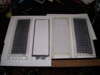
right now I am using my little panels of 3.25" X 9.75" diagphram size with a d/s of around .070" to .075" (i think it was .072").
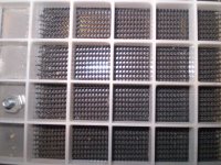
this is the exploded view and a close up of the stator.
jer
this is the exploded view and a close up of the stator.
jer
Attachments
Last edited:
here is some more pics and the setup I was referring to.
http://www.diyaudio.com/forums/planars-exotics/158115-material-esl-2.html#post2075441
There are a bunch more.
I guess I need to take the time and recompile my list of links and put it in the permenent thread.
http://www.diyaudio.com/forums/plan...nstruct-cube-louver-acoustat.html#post2142851
http://www.diyaudio.com/forums/planars-exotics/109789-esl-diaphragm-coating-7.html#post2143748
jer
Last edited:
Hi Dochungwell,
To make a pair of hybrid ESL, following what Jazzman's construction technics can't go wrong. About the spacer thickness, I think 1 to 1.5 millimeters is good enough. The bias voltage can be around 2-2.5KV for each 1 mm.
Good luck.
Wachara C.
To make a pair of hybrid ESL, following what Jazzman's construction technics can't go wrong. About the spacer thickness, I think 1 to 1.5 millimeters is good enough. The bias voltage can be around 2-2.5KV for each 1 mm.
Good luck.
Wachara C.
I also have a newbee question :
How do you test the output voltage ?
I tried even with a 10M high voltage probe.
It still overloads the circuit too much, that I get nowhere near the 2kV i expected.
Thx,
Patrick
How do you test the output voltage ?
I tried even with a 10M high voltage probe.
It still overloads the circuit too much, that I get nowhere near the 2kV i expected.
Thx,
Patrick
Hi,
10Meg is the typical impedance of a multimeter and way too low to measure HV of a Bias supply. The currents are too large and the load forces the voltage down. For measuring HV think of impedance values in the Giga-range. Simplest is to solder a chain of 100 pcs of 10Meg resistors and measure the voltage over one or a couple of the ´lowest´ resistors and calculate the voltage after the resistor-divider-formula Vmes=Vbias*Rmes/Rcomplete (with Rmes beeing the parallel from the resistor measured over and the multimeters internal impedance).
This method doesn´t give exact values, but You are close enough.
jauu
Calvin
I used a a large string of about 10 X10M resistors as a voltage divider it still loaded it down.
But not as bad as I am sure my supply produces more than 7.5kv.
But that was the peak voltage I got with the resistor divider hook up as it was all I needed any how.
Any more than that just caused the air too breakdown in between the diagphram and stator.
jer
But not as bad as I am sure my supply produces more than 7.5kv.
But that was the peak voltage I got with the resistor divider hook up as it was all I needed any how.
Any more than that just caused the air too breakdown in between the diagphram and stator.
jer
I used a a large string of about 10 X10M resistors as a voltage divider it still loaded it down.
But not as bad as I am sure my supply produces more than 7.5kv.
But that was the peak voltage I got with the resistor divider hook up as it was all I needed any how.
Any more than that just caused the air too breakdown in between the diagphram and stator.
jer
Hi Jer,
I too was thinking of building adjustable/low ripple bias supplies using those little EMCO modules but their cost put me off. Besides, I want to keep whatever I post on my blog page simple and dirt cheap for the sake of the broke and electronically challenged, like myself.
This past weekend, though, I modified my current bias supplies by adding two more diode/cap stages and upping the output resistor from 11 Mohms to 18 Mohms. And $23 for a bias supply is cheap enough even for me (lol). I can’t measure the output voltage but I figure 120 volts into the tranny gives 240 volts out, times (8) diode cap stages should give about 1,920 volts output (versus 1,440 volts from the previous 6-stage ladder). Does that sound about right?
For comparison, I first modded the bias supply to just the right speaker; which then played noticeably louder than the left speaker. With the speaker energized but no music playing I placed my hand on the front stator and felt intermittent tingling in my fingertips from tiny arcs leaping off the diaphragm into my fingers; whereas, I did not feel the same tingling in my fingertips from the left speaker.
I’m sure any half-wave 60hz bias supply would have a ton of ripple but it’s certainly not audible in my speakers (I figure you would never hear it unless the diaphragms were leaking charge badly). Also, I don’t hear any buzzing or other indications that the bias is too high so I figure it’s OK.
I’ve now modded the bias supplies in both speakers and they sound as wonderful as ever except they now have a bit more sensitivity. What I don’t yet know is how well the diaphragm coatings and electrical contacts will hold up to the higher bias voltage over time. Should I be concerned about this?
Charlie
(Jazzman)
Attachments
Last edited:
Yes,very good,Charlie, I am glad that you had finaly tried this.
Theoriticaly you should should have about 2.7kv=1.41 X 8 X Vin(240).
But do to the losses it probably around 2.2kv to 2.5kv.
As each time you add a stage the voltage gets more but the losses are greater aswell.
I have a very good online calculator buried in my data somewhere and I will try to find it and post it for you as it seems to be fairly acurate.
Acording to a graph that bolserst posted I found it to be true that for every doubling of the bias voltage you gain 6db of efficientcy which is why I was striving to be able to conceal such high tension.
Using my variable supply there was a big difference between the 2kv to 3kv range compared to an all out of 6kv and higher.
And then when I doubled the transformation ratio (another 6db) the thing was smokin loud (pun intended aswell he,he,he)!!
I found that the 5kv to 6.5kv range was all the thing could handle before any risk of arcing and catstrophic failures and fire as I had described earlier.
You shouldn't have any problem the your contacts or diagphram coating.
As the new formula that we are using is much more flexible than the old stuff.
When I used the old stuff I had one instance were a crack formed at the edge of the frame and caused an open circiut and the diagphram would not charge because of it.
To remedy this I would coat the borders a little thicker.
But since then I have been using a charge ring aswell as a backup should any cracks occur along the border of the frame were the flex point is.
Also the coating we are using has a much higher resistance than the old formula so if any arcing to the diagphram should occur the current is low enough that it does not burn any holes in the mylar.
After I thought that had destroyed that one panel I found that there were no holes burned in the mylar.
If there were I could not find them with my magnifying glass.
This was not true with the panel using the old formula subjected to the same tests and abuse.
jer
I too was looking at the emco modules and the are quite costly.
But I like their little tiny one as it is adjustable and can be mounted directly on the frame as it is so tiny!
jer
But I like their little tiny one as it is adjustable and can be mounted directly on the frame as it is so tiny!
jer
On my first supply I used a 60hz source and the only time I got hum was when I was trying different taps and when I selected one that was on the same side as the ground lead.
So as long as you stay on the oppisit side of the ground (to the stepup transformer) you shouldn't have any hum problems as there is not enough current drawn off of the supply for it to be an issue.
jer
So as long as you stay on the oppisit side of the ground (to the stepup transformer) you shouldn't have any hum problems as there is not enough current drawn off of the supply for it to be an issue.
jer
I can\u2019t measure the output voltage but I figure 120 volts into the tranny gives 240 volts out, times (8) diode cap stages should give about 1,920 volts output (versus 1,440 volts from the previous 6-stage ladder). Does that sound about right?
If you can measure the output of your bias supply transformer and confirm the voltage as 240Vrms, then the output of an unloaded 8x voltage multiplier will be:
240 x sqrt(2) x 8 = 2,700 Volts
The sqrt(2) = 1.414 factor gives you the peak voltage of the 240Vrms waveform.
This is approximately what the first capacitor will be charged to. Each successive capacitor being charged to twice this value.
With the usual small amounts of leakage in a well built ESL you could expect the actual voltage to drop 5% or so from the peak calculated value.
Thanks guys! I'm very happy with the new bias supplies, as I'm getting very high sound output from my panels and they sound fabulous.
I also have a newbee question :
How do you test the output voltage ?
I tried even with a 10M high voltage probe.
It still overloads the circuit too much, that I get nowhere near the 2kV i expected.
Thx,
Patrick
Patrick, glad to see you're playing with ESLs, in your "free time"..... I know you're very busy with the F5X (and thanks).
Concur, with the use of the multiple 10Mohm (or higher) resistor chain. This is about the only way practical way to measure the ESL stator voltages. I use about a 1 Gohm input, into a FET diff op amp, and then into a typical DMM. The resistor chain and FET diff op amp provide such a high imput impediance that they place very little load on the ESL supply.
I currently have a pair of Martin Logan Sequel panels that I've rebuilt, and getting ready to build 15" TL woofers to mate with them. Fun times, again!
Thanks everyone who has responded to my post. I have literally spent the entire weekend reading nearly the post in this forum (im half way there), and also sourcing parts.
With regards to the EMCO G-40 module, they do not sell to the general public...too bad for me, it would have cost a couple of bucks, but it would have been a breeze to experiment with!
Charlie, thanks for you well chronicled build. I actually printed you blog and using if as a guide for my build. I am also happy to hear your circuit modification was successful in increasing sensitivity and volume. This I will note for my build! I do however have a question in regards to your mechanical stretcher. I am still not clear as to the optimal stretching distance. Is the distance essentially a 4-5mm shift from the table alignments marks compared to that of the film’s reference marks using (c 6um). This will likely be the only thing I will have the most difficulty with. I can only compare the tension with my Magnaplaners tension, which sounds like a drum when you thump it. I’m guessing this is what I am trying to achieve…with more tension?
BTW, I have scaled down my original plans of my panels to 18”x24 which may be further reduced since the film is just slightly over 24”.
Jerry
- Status
- Not open for further replies.
- Home
- Loudspeakers
- Planars & Exotics
- Newbe Question: ESL bias power supply