Hi there,
I have a (possibly stupid) question concerning the negative rail of my tube-rectified power supply: Does the following make sense or is there something wrong with that plan?
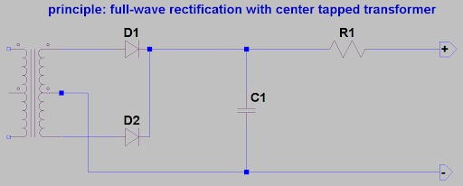
So here it is, step one: A center tapped full wave rectifier circuit with a simple reservoir cap and a series resistor. This is well-known and produces a voltage with the given polarity between the two output terminals.
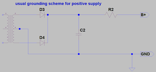
The second step is easy: Attach an earth connection to fix the lower leg to earth potential, take the B+ from the upper leg.
The basic circuit shown in the first picture works without ground connection, it produces a voltage difference between the output terminals. The earth connection is needed to tie the circuit to a defined reference potential. Now, what if we tie the upper leg to ground? The lower output terminal should be at a negative voltage relative to ground, then:

Now, for the final step, change the filter components to the leg where the B- is taken from. This should be a valid negative supply rail.

Is this correct or will I produce lots of smoke in trying it out? 😀
Greetings,
Andreas
I have a (possibly stupid) question concerning the negative rail of my tube-rectified power supply: Does the following make sense or is there something wrong with that plan?
So here it is, step one: A center tapped full wave rectifier circuit with a simple reservoir cap and a series resistor. This is well-known and produces a voltage with the given polarity between the two output terminals.
The second step is easy: Attach an earth connection to fix the lower leg to earth potential, take the B+ from the upper leg.
The basic circuit shown in the first picture works without ground connection, it produces a voltage difference between the output terminals. The earth connection is needed to tie the circuit to a defined reference potential. Now, what if we tie the upper leg to ground? The lower output terminal should be at a negative voltage relative to ground, then:
Now, for the final step, change the filter components to the leg where the B- is taken from. This should be a valid negative supply rail.
Is this correct or will I produce lots of smoke in trying it out? 😀
Greetings,
Andreas
It is usually better to reverse the two diodes and keep the middle of transformer to ground.
Why? Because you could make simultaneous + and - rails that way...
Why? Because you could make simultaneous + and - rails that way...
It is usually better to reverse the two diodes and keep the middle of transformer to ground.
Full ack. But this is not so easy when tube rectifiers with a common cathode are used - thats why I want to use the schematic above...
Greetings,
Andreas
Full ack. But this is not so easy when tube rectifiers with a common cathode are used - thats why I want to use the schematic above...
Greetings,
Andreas
Hi Andreas,
What you propose in your last schematic will work just fine with a tube rectifier. The only issue is that what you have drawn is not an RC filter, you need to place the cap after the resistor for that to be the case or make a CRC filter which might be what you intended. (Add a cap between the output and ground) Flip cap polarity if using electrolytics!
 😀
😀what is the purpose of the -ve rail ie what is it supplying? And how does it fit wit hteh rest of your power supply scheme?
You may cause excessive insulation stress if this is for HT supply. Instead of the maximum voltage stress of a portion of secondary (either Tx winding or valve terminal or wire) being peak half winding voltage wrt ground, it is now twice that level.
Electrolytic can cases are also nominally at or near the negative terminal potential - which would now not be at ground level but at (-) HT level. Similar to the 'top' cap in a series connection often used with doubler rectifiers. A problem that has surely given a belt or two to any unwary service tech.
Ciao, Tim
I've seen several tube circuits with the anode at ground and the cathode at a negative voltage.
I don't know if this is more information than you asked for, but for anyone that is not too familiar with the problem:
With a transformer isolated supply, you can tie either side to ground and get the difference in potential at the side not tied to ground. Any number of transformer isolated supplies like this can all have one of their rails tied together and to ground and you can get a variety of voltages, positive and negative, at the other rail of each supply all of which can be used in the same circuit. There will be no difference in voltage inside the transformer relative to itself, save what is caused by the loading of the circuit.
The way you have the circuit drawn, the cap will charge to the peak voltage and the resistor will act as a current limiter and also as a voltage divider with the resistance of the circuit connected to it. You need a second cap after the resistor that will charge to the peak voltage allowed by the voltage division and act as a ready reserve of power for the circuit to be powered. However, it will be limited as to how fast it can recharge by the current limiting action of the resistor. If the value of the resistor is low relative to the resistance of the attached circuit, the voltage drop will be small. A simple power supply uses a transistor or regulator in place of the resistor that can track the current and change its resistance to keep the voltage steady.
It is common in most circuits to add a cap to the supply line near the pins of each stage in a circuit to help keep the supply current steady to each stage and unaffected by the other stages. The size of the cap depends on the voltage of the supply and the current draw of the stage, with one chosen as a compromise between filtering capacity and physical size or cost.
The polarity of the capacitor will still be correct, don't flip it. Always keep the can of an electrolytic cap at the lower potential side, or you will be suddenly surprised! (in the "don't try this at home" category)
what is the purpose of the -ve rail ie what is it supplying? And how does it fit wit hteh rest of your power supply scheme?
Hi aardvarkash10,
the purpose of the -ve is to supply a pentode CCS below the diffential pair of a driver stage. It does not carry much current, only about 8mA @180V per channel...
It does not interfere with the rest of the power supply, as I included separate HT and heater windings for it...
Greetings,
Andreas
As drawn it will work fine, your power transformer is quite agnostic as to the polarity and voltage levels on its windings as long as the insulation voltage ratings are not exceeded. (And at those voltages they won't be - at a kV or more it may become a valid concern)
As long as you are not using FP (chassis mount) electrolytics you have no issue with the case either. Snap ins and axial types all have floating cases - not that I recommend ever touching them when the circuit is energized as there may be leakage current present.

- Status
- Not open for further replies.
- Home
- Amplifiers
- Power Supplies
- PSU sanity check - negative rail?