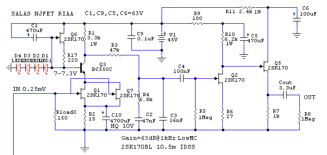
R5=220K terminal resistor, not 200R trimmer. You have to use 550, it sets the voltage lower also. Plus, its not going to play long on batteries. 14mA bias.
that what I'm afraid of 🙂, making another supply is unavoidable. back to the bench then. btw, R1 180R replaced by trim 200R, R5 220k under the board,
thanks
TeguhPS
Yep, but give it a check as it is now on batteries to see if you have any other issues, trim your gain, its a good opportunity now its assembled as it is.
yes after I'll give me and my MM cart 1-2 days chance ha ha, before I messing up the setup for MC ..will let you know how it sound, thanks again Salas
Hi MerlinYes new longer listening session & your very good tweak/advice getting off the resistor & capacitor is a very huge upgrade, remember me near the same subjective than getting off the cap in the 1st stage but the cap in the 1st stage was still worse. Output caps Mundorf Silver Gold in oil are very very transparents so I can hear very easy the differences to god or bad.
😉
I do not have caps on the first and second stages and that is surelly the way it sounds better... Any cap there leaves a heavy signature.
I guess it would be even better to try no cap on the buffer... but in that case, in order to avoid the buffer starving the previous stages, it would be better to use another shunt only for this.
PS:
Are you using a balanced riaa ?
Hi Merlin
I do not have caps on the first and second stages and that is surelly the way it sounds better... Any cap there leaves a heavy signature.
I guess it would be even better to try no cap on the buffer... but in that case, in order to avoid the buffer starving the previous stages, it would be better to use another shunt only for this.
PS:
Are you using a balanced riaa ?
Lytics caps are evils for good sound.
That's will be a solution but it's a little expensive one shunt reg + psu caps & tx only for the buffer.
I'm using SE RIAA post 2795 page 280
Hi,
I can understand why you have disabled R9 & C5 when using a quiet and well regulated supply for V1.
I cannot understand why you need to disable/remove C10. Could you explain?
What have you done with
I can understand why you have disabled R9 & C5 when using a quiet and well regulated supply for V1.
I cannot understand why you need to disable/remove C10. Could you explain?
What have you done with
Wich gain have now the schematic I'm using without C10 4700uF, R9 100R (jumper) & C5 470uF?
I don't have it in my files anymore as I have replied you previously but it should be around 57-59dB now give or take the real Yfs of your JFETS if measured as a whole with precise input signal. Towards 59 more likely.
He did not need in the end the gain he initially asked for might be a plausible scenario?
My Denon DL103R real output 0,29mV instead 0,25mV
Hi,
I can understand why you have disabled R9 & C5 when using a quiet and well regulated supply for V1.
I cannot understand why you need to disable/remove C10. Could you explain?
What have you done with
Because I hear better.
Because don't need more gain.
I don't have it in my files anymore as I have replied you previously but it should be around 57-59dB now give or take the real Yfs of your JFETS if measured as a whole with precise input signal. Towards 59 more likely.
What's Yfs? Idss is 10.5mA
What's Yfs? Idss is 10.5mA
Transconductance. I.e. intrinsic gain potential.
Transconductance. I.e. intrinsic gain potential.
Thanks for letting me know, I don't know.
Hi,
I can understand why you have disabled R9 & C5 when using a quiet and well regulated supply for V1.
I cannot understand why you need to disable/remove C10. Could you explain?
Hi Andrew
I built a 57dB machine and used C10 (4700u) to get it to 61dB but I clearly heard a diffused/boxed sound probably coming from the EL cap signature.
IMO the first stage jfet source is determinant to the overall low noise and definition. I did not like the cap there.
I remenber Merlin did not like the sound with the cap there also.
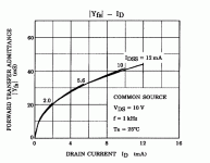
There is a chart that shows its relationship trend to ID (if ID=IDSS when Rs=0 amounts to the same) in most Toshiba low noise JFETs data sheets. We have referred before here, but I remind for K170.
Hi Salas
From that chart we might deduce a higher Idss jfet has higher transcondutance.
A higher transcondutance means more Volt/current amplification potential right ?
If so, why not use only high Idss jfets instead of the average 8.5mA you calculated ?
- Home
- Source & Line
- Analogue Source
- Simplistic NJFET RIAA

