Sir 'faster' in the sense?
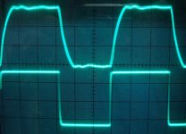
'Slow' and 'fast' with 20kHz square wave.
Attachments
Set Bias
I've just build AX-14 with 32 Vac supply voltage,but hard to set bias to find 2V on R10 Ohm insted fuse....Why???
Regards
I've just build AX-14 with 32 Vac supply voltage,but hard to set bias to find 2V on R10 Ohm insted fuse....Why???
Regards
'Slow' and 'fast' with 20kHz square wave.
what is the value of cap when it is slow at the time of testing
Last edited:
I've just build AX-14 with 32 Vac supply voltage,but hard to set bias to find 2V on R10 Ohm insted fuse....Why???
Regards
Try to set 0,5V-1V on 10R, with 2V bias will be 200mA, it's to high. Start with 50mA (0,5V on 10R), and check heatsink temperature after 10min.
Regards
You want to build 500W Hi-Fi amp😕
I must draw schematic for this version, than I will share PCB
Regards
Have you draw this project Sir???
Regards
what is the value of cap when it is slow at the time of testing
Values from post #1.
Try to set 0,5V-1V on 10R, with 2V bias will be 200mA, it's to high. Start with 50mA (0,5V on 10R), and check heatsink temperature after 10min.
Regards
I've adjust bias 50mA and it works now....very2 clear sound....

I use 32VAC supply........heatsink temperature is normal.......
What is the minimun load impedance for AX-14??
How to get more bass???
Regards
I've adjust bias 50mA and it works now....very2 clear sound....
I use 32VAC supply........heatsink temperature is normal.......
What is the minimun load impedance for AX-14??
How to get more bass???
Regards
Nice, but can you post pictures?
Minimum load is 4ohm.
I made this amplifier for test my home DIY speakers (two way TL).
I remember seeing that layout in a kit amp , attached .
Where did you get that though ?
Attachments
I remember seeing that layout in a kit amp , attached .
Where did you get that though ?
There is nothing similar with circuit in your attach and AX14, I don't understand your question😕
There is nothing similar with circuit in your attach and AX14, I don't understand your question😕
No , the circuit is very , very similar , except for a few changes .
Well , i have the PCB here .
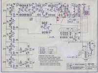
Hi everybody, i just analysed Ax14 circuit with SPICE simulator. everything is ok upto
pre- drivers. voltage at base of driver Q11 shows -1.25 V but base of Q13 shows only
+ 0.680V. i am expecting help from apex and other experts. kindly reply. (sorry for bad
english)
pre- drivers. voltage at base of driver Q11 shows -1.25 V but base of Q13 shows only
+ 0.680V. i am expecting help from apex and other experts. kindly reply. (sorry for bad
english)
No , the circuit is very , very similar , except for a few changes .
Well , i have the PCB here .
'Very, very similar' 'few changes'... but any stage is different, PCB also, I think you post in wrong thread.
Hi everybody, i just analysed Ax14 circuit with SPICE simulator. everything is ok upto
pre- drivers. voltage at base of driver Q11 shows -1.25 V but base of Q13 shows only
+ 0.680V. i am expecting help from apex and other experts. kindly reply. (sorry for bad
english)
Help you to build this amplifier or help you to simulate this amplifier, can you post pictures or files from SPICE simulator?
'Very, very similar' 'few changes'... but any stage is different, PCB also, I think you post in wrong thread.
I was implying that company copied your design , with similar parts and the same exact inductor values 🙂
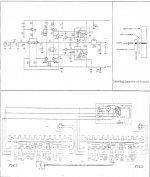
Sir
could you please tell me what are RP401 and RP501 used for in the attached schematic
2 VR's / Pots , that's the standard schematic design .
Sir
could you please tell me what are RP401 and RP501 used for in the attached schematic
Variable Resistors 22k and 470 ohm.
I was implying that company copied your design , with similar parts and the same exact inductor values 🙂
What company? I still not understand...
- Home
- Amplifiers
- Solid State
- 100W Ultimate Fidelity Amplifier