Cheers Labjr.
I found these:
400V 25A Bridge Rectifier
For the full wave rectifier. What do you think? Is it worth spending more for say "Vishay" units or does it make no difference?
Thanks again
Dean
I bought these on ebay.
1 x SEP KBPC5010 Metal Case 50A 1000V Bridge Rectifier - eBay (item 220631167584 end time Mar-29-11 00:14:59 PDT)
I haven't tried them yet but I think all the standard bridge recifiers are about the same until you get into the expensive IXYS fast recovery types.
Hi,Umm, can you use a 18-0-18 transformer???
I thought you must have a 0-18,0-18 so that you can have 2 rectifier blocks...
Can you have two bridge rectifiers on a center-tapped transformer? I honestly don't know,
a centre tapped transformer can be connected to a single bridge rectifier and the loss of DC at the rail to rail output is 1.4V
A dual secondary can be converted to a centre tapped and end up with exactly the same DC voltage rail to rail.
However, a dual secondary can be used with a dual bridge rectifier and when the two DC supplies are series connected the loss of DC at the rail to rail output is 2.8V
If you want the same supply voltage from a dual bridge arrangement the dual secondary transformer must be selected to be 1Vac higher, i.e. 18-0-18Vac gives the same Rail to rail DC voltage as a 0-18.5+0-18.5Vac, dual rectifier, dual secondary transformer.
Note that the 2.8V of loss means the total heat to be dissipated by the dual bridge rectifiers is exactly double that of the single bridge rectifier arrangement.
Ok! More progress! It's actually looking like an amp now... 😀
The holes in the heatsinks are slightly countersunk and de-burred. I smoothed out the area near the heatsink interface with a foam emery board, it should help thermal conductivity, even if just a little. It may look scratch in the photo, but it is noticeably smoother to the touch than the stock surface.
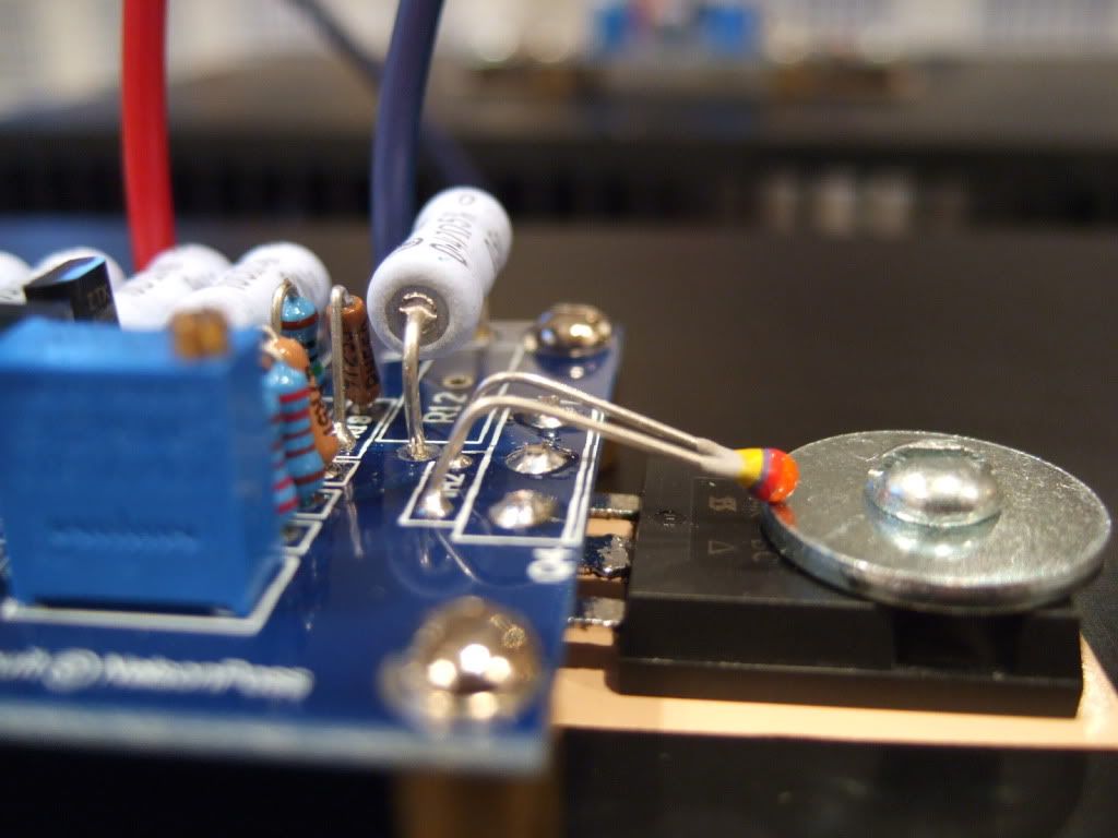
The transistors are soldered, the thermistors are bent and touching the washer. I don't see any reason to glue them.
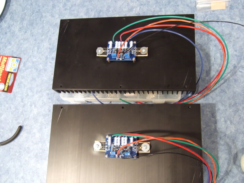
Here is a photo of the final assembly of the 2 amp channels. Hopefully I will never need to take these apart again.
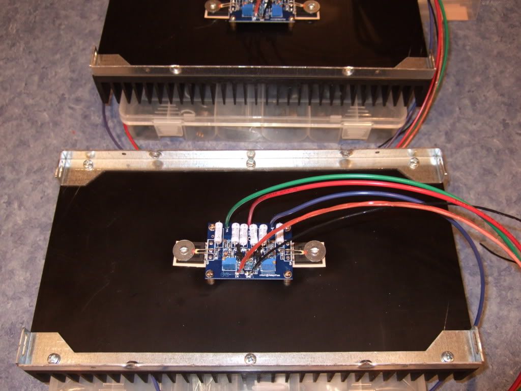
These brackets are part of the chassis.
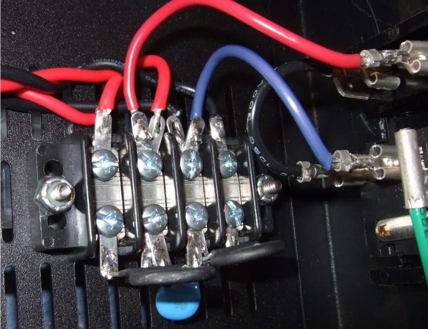
This is the mains connection, from the back of the power inlet module. Red is hot, it is switched and fused. Blue is neutral.
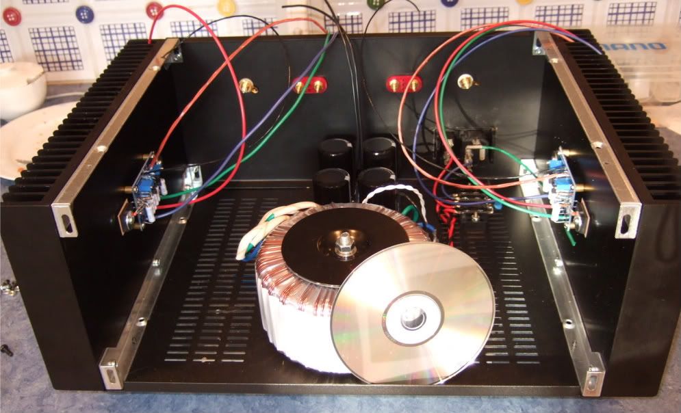
Hey look! It's starting to resemble an amp!
Obviously, the CD is for scale.
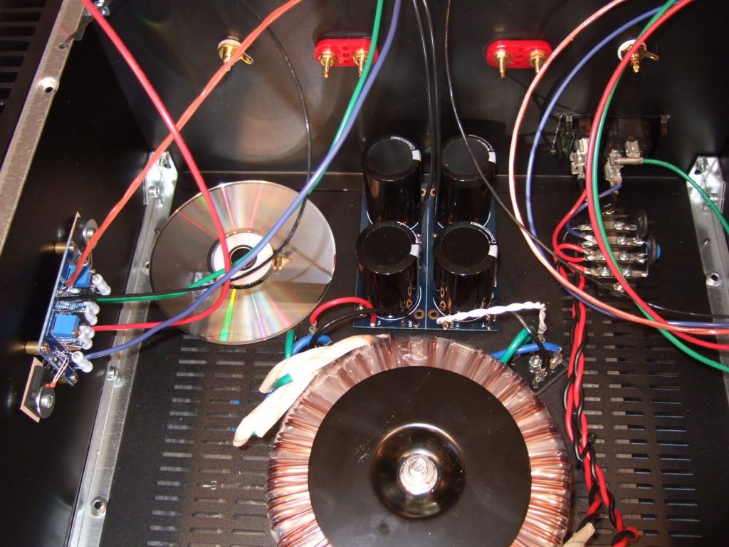
This channel is completely wired.
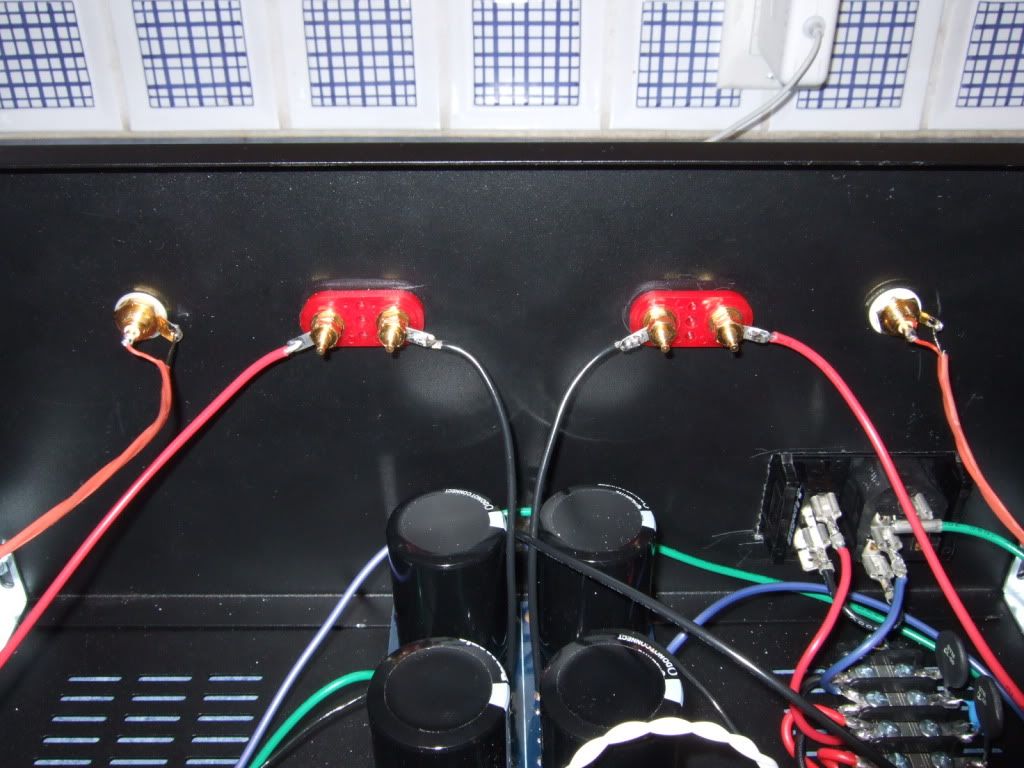
The back panel. Yes, the speaker negatives come from the PSU board.
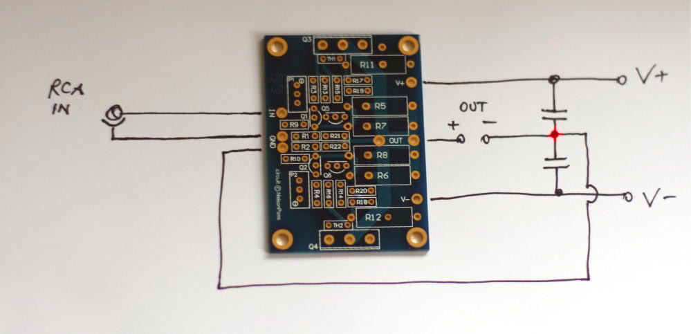
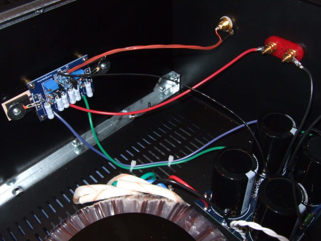
This is the way the PSU board is hooked to the amp board. (Image courtesy of Peter Daniel)
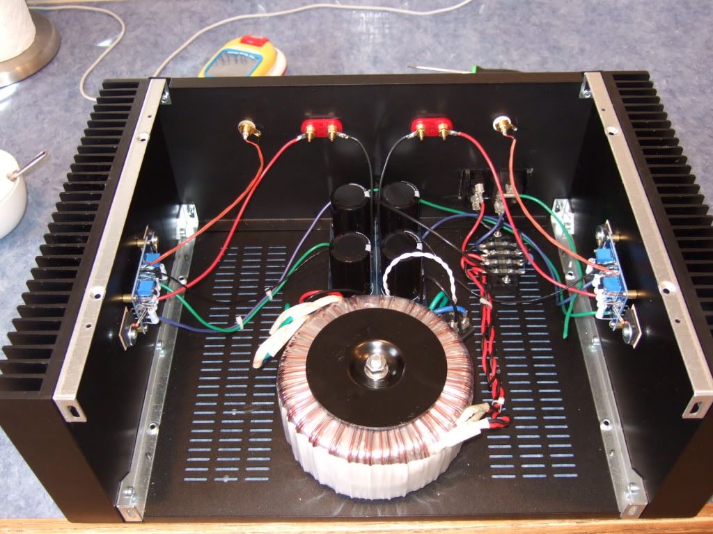
Here is where I left it today -- the left amp channel is wired and finished. The opposite is wired, but needs the wires dressed. The PSU board is complete except for the connection to chassis ground via the last CL-60 thermistor. The AC inlet is also in need of the safety lead connected to chassis ground.
The holes in the heatsinks are slightly countersunk and de-burred. I smoothed out the area near the heatsink interface with a foam emery board, it should help thermal conductivity, even if just a little. It may look scratch in the photo, but it is noticeably smoother to the touch than the stock surface.
The transistors are soldered, the thermistors are bent and touching the washer. I don't see any reason to glue them.
Here is a photo of the final assembly of the 2 amp channels. Hopefully I will never need to take these apart again.
These brackets are part of the chassis.
This is the mains connection, from the back of the power inlet module. Red is hot, it is switched and fused. Blue is neutral.
Hey look! It's starting to resemble an amp!
Obviously, the CD is for scale.
This channel is completely wired.
The back panel. Yes, the speaker negatives come from the PSU board.
This is the way the PSU board is hooked to the amp board. (Image courtesy of Peter Daniel)
Here is where I left it today -- the left amp channel is wired and finished. The opposite is wired, but needs the wires dressed. The PSU board is complete except for the connection to chassis ground via the last CL-60 thermistor. The AC inlet is also in need of the safety lead connected to chassis ground.
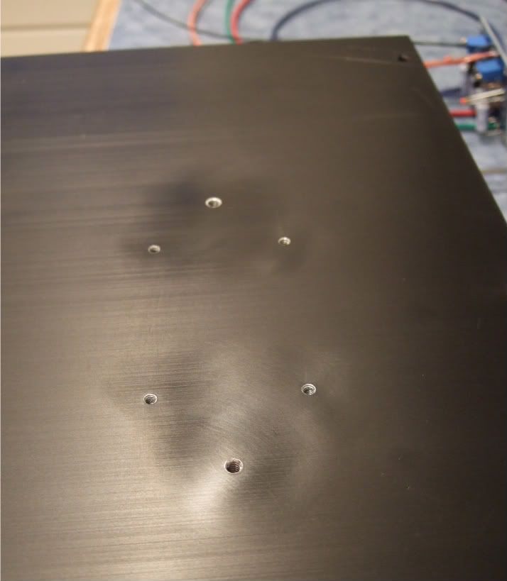
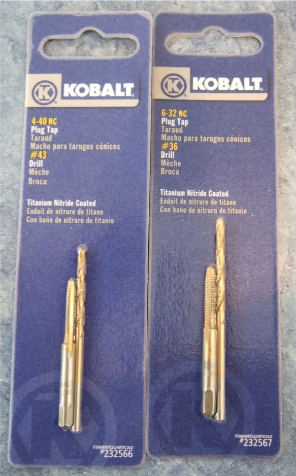
I've got to drill and tap 2 holes for 6/32 standoff and screw.
What size drill bit should I be using to drill this pilot hole out.
Any suggestions?
I've got a scrap piece of heatsink I can experiment on.
What size drill bit should I be using to drill this pilot hole out.
Any suggestions?
I've got a scrap piece of heatsink I can experiment on.
Hi 6L6
Nice work.
Just want to mention something here. On your terminal block you have a red and black solder lug very close to each other.
It would be nice to give them a bit more space.
Nice work.
Just want to mention something here. On your terminal block you have a red and black solder lug very close to each other.
It would be nice to give them a bit more space.
I've got to drill and tap 2 holes for 6/32 standoff and screw.
What size drill bit should I be using to drill this pilot hole out.
Any suggestions?
I've got a scrap piece of heatsink I can experiment on.
here is a pdf drill chart
http://www.imperialsupplies.com/pdf/I_DrillSizeDecimalEquivalent&TapDrillChart.pdf
jim
I've got to drill and tap 2 holes for 6/32 standoff and screw. What size drill bit should I be using to drill this pilot hole out.
Looking at the package that my tap was in, it seems to be a #36.
Melon head said:Just want to mention something here. On your terminal block you have a red and black solder lug very close to each other.
It would be nice to give them a bit more space.
Good point. I will re-set them in the screw so they are not as close. Thanks!
Hi 6L6
Nice work.
Just want to mention something here. On your terminal block you have a red and black solder lug very close to each other.
It would be nice to give them a bit more space.
6L6....Jim, My pic on post #300 on your thread might be useful. On my barrier strip, I used three types of lugs--0 degrees (spade terminals are parallel to the bottom chassis plate), 45 degrees, and 90 degrees (spade terminals slip on from the vertical plane). Not all that easy to tell, from my pic.
By doing so, I didn't have to "fan out" multiple connections on a terminal. Instead, I was able to stack them with a mix-match of the 0, 45, and 90 degree lugs. Prevented lugs attached to adjacent terminals from getting too close together.
Ken
Kevin -
Yes, I see what you are getting at. Placing a slight bend in the terminal lugs will be very easy and will accomplish something similar to what you have with the various lugs.
Yes, I see what you are getting at. Placing a slight bend in the terminal lugs will be very easy and will accomplish something similar to what you have with the various lugs.
6l6..... Yep. A pair of needle-nosed pliers, a suitable "adult beverage" and about 20 seconds is all you need to make this modification!
Ken
Ken
I have many choices of single-malt (scotch) whisky... I wonder which would be the most appropriate... 🙂
6L6...... Awwww--screw all this DIY audio stuff......! Let's break out the Glenfiddich....!
I discovered a LONG time ago, generous applications of "single malt" will even make an integrated Sansui amp sound fantastic..... although the next morning, I couldn't recall what I was listening to..... 😀
I discovered a LONG time ago, generous applications of "single malt" will even make an integrated Sansui amp sound fantastic..... although the next morning, I couldn't recall what I was listening to..... 😀
I honestly don't know for sure, but it's probably 16 or 18 gauge -- I just bought it at the surplus store... It looked to be a good size, not too big, and it fit in the holes of the PSU board. It does need to be trimmed a bit to fit in the amp board.
okay, i'll be wiring all of my amplifier with i think 16 gauge, i just wanted to make sure it would all be sufficient!
don't know for sure, but it's probably 16 or 18 gauge
Back in the old days, more than a few pro designers had trouble picking gauge size for the board gnd to star ground wire.

Initial testing of the F5--great info.....!
6L6, Woody, etc.....
I got this info today from Zen Mod regarding "firing up" the F5 and setting the bias. It's the most detailed and informative (and practical) info I've seen on the subject. I wanted to pass it along, as we collectively get close to "turning on the big switch". Great info...!
From Zen Mod:
dial both pots to 0 ohms ( check with ohmmeter )
place one voltmeter across PSU caps ( best between + and - of PSU) to observe max voltage of PSU
place one voltmeter at output - to observe offset
place one voltmeter across one source resistors of output mosfets ; it doesn't matter which one .
for test - slowly dial up Variac ( presuming that you have one , as man with many skills) up to full mains voltage , observing voltage at PSU ....... thinking about max cap voltage ( 25V as in FW ? ) , because with 0 Iq PSU is unloaded and voltage is maxed
if nothing is smelling - leave Variac at full mains ;
what's important - Iq must be very low , offset is irrelevant in this moment .
now turn one pot one turn ( assuming that you have multiturns )
then turn other pot one turn
observe Iq and offset
proceed one then second pot , again just one turn
observe Iq and offset
again one turn + one turn
now you are probably in range when you can see which pot is pulling offset in right direction - to 0 .
proceed iteratively with pots , while you set - say - 75% of desired Iq and zero offset
now - put lid on box and let it cook for a while - until yo get thermal equilibrium on heatsinks
it's best to use wire/clips to leave those voltmeters in place ;
open the lid , up bias to - say - 90% of desired one ,while maintaining offset
put lid on , let it cook
check ;
if all is OK - move voltmeters for Iq and offset to other channel and repeat procedure
use it few days at 90% of desired bias , then check and set to 100%
remember - temp. equilibrium with lid on is important
simple , isn't it ?
Looking at the package that my tap was in, it seems to be a #36.
Good point. I will re-set them in the screw so they are not as close. Thanks!
Great, I'm going to look for this drill bit and tap kit (on ebay).
- Home
- Amplifiers
- Pass Labs
- How to build the F5