Right gang,
Think it is about time I start my own build thread, this one is slightly different. Maybe. 😉
The background here is that I have never owned a 'proper' SE amp, and would very much like to hear one. At the same time I'd like for the components to be generally useful, if for some reason I find a design wanting and wish to build something else entirely. So the most expensive parts herein could for instance easily be reused in a more usual KT88 SET amp, which many forum members seem to like.
I won't be ordering any parts within the next couple of days in any event, so there should be plenty of time to shoot my contraption down in flames as needed, or suggest modifications or alternatives.
*) This design is heavily inspired by the RH84 SE. I like to run my stuff quite conservatively, thus I plan on using a gently nudged KT88 in place of a sweating EL84. No, I have no idea what this will sound like. 😀
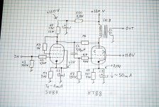
*) No tools beyond datasheets, pocket calculator and a ruler has been used on the design at this point. It is likely to need tweaking, particularly the load line (which has been scaled a bit to 110V screen grid voltage). Power output is about 7W or so.
*) Some features has unashamedly been nicked from SY's The Red Light District: The large grid stopper to limit grid current on overload, and a very stable Maida type KT88 screen grid voltage regulator, tweaked to accommodate the larger voltage drop across it.
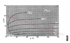
*) Found the measured curves for a triode strapped SV83 somewhere on the net. Va = 100V @ Ik = 8mA, Rl = 18K looks to be a nice, sweet spot regarding linearity. The 18K is seen as being implemented via R5 in parallel with R8.
*) Intend to experiment with other forms of bias, maybe including some variation of SY's LED array with accommodations for the large current swings found in SE class A operation. Other experiments may include Tubelab's Superdrive, or running the SV83 as pentode to allow for more feedback etc.
*) V1 provides about 15 times of voltage amplification in this configuration. This leaves enough headroom for about -5dB of NFB via R6 (to be determined).
*) V2 idles at about 50mA, 16W of continuous dissipation. Should make it last a while... 😉
*) Will use Svetlana(EU) / Winged-C (US) KT88s from St. Petersburg, and SV83s plus a 5U4G equivalent from the same location. Thus the name for the contraption.
*) Have a Hammond 370HX mains transformer on hand: 2x 275V @ 200mA plus heaters, claimed to be 180VA. Ought to be able to provide a total of about 120 mA for both channels.
*) R5 is a 25W unit only because it makes it easy to bolt it to the chassis or onto a heatsink.
*) Output transformers will be bought powerful enough so they may be reused in, say, a KT88 SET if needed. 5K:8 seem to fit many tubes and configurations, though a 'large' transformer may not have quite enough primary inductance to fully reproduce the lowest frequencies in a pentode configuration.
OK, do your worst. 😎
- Frank.
--
Edit: Screen grid voltage needs to be around 120V to compensate for the loss across the cathode resistor, of course. 😱
Think it is about time I start my own build thread, this one is slightly different. Maybe. 😉
The background here is that I have never owned a 'proper' SE amp, and would very much like to hear one. At the same time I'd like for the components to be generally useful, if for some reason I find a design wanting and wish to build something else entirely. So the most expensive parts herein could for instance easily be reused in a more usual KT88 SET amp, which many forum members seem to like.
I won't be ordering any parts within the next couple of days in any event, so there should be plenty of time to shoot my contraption down in flames as needed, or suggest modifications or alternatives.
*) This design is heavily inspired by the RH84 SE. I like to run my stuff quite conservatively, thus I plan on using a gently nudged KT88 in place of a sweating EL84. No, I have no idea what this will sound like. 😀
*) No tools beyond datasheets, pocket calculator and a ruler has been used on the design at this point. It is likely to need tweaking, particularly the load line (which has been scaled a bit to 110V screen grid voltage). Power output is about 7W or so.
*) Some features has unashamedly been nicked from SY's The Red Light District: The large grid stopper to limit grid current on overload, and a very stable Maida type KT88 screen grid voltage regulator, tweaked to accommodate the larger voltage drop across it.
*) Found the measured curves for a triode strapped SV83 somewhere on the net. Va = 100V @ Ik = 8mA, Rl = 18K looks to be a nice, sweet spot regarding linearity. The 18K is seen as being implemented via R5 in parallel with R8.
*) Intend to experiment with other forms of bias, maybe including some variation of SY's LED array with accommodations for the large current swings found in SE class A operation. Other experiments may include Tubelab's Superdrive, or running the SV83 as pentode to allow for more feedback etc.
*) V1 provides about 15 times of voltage amplification in this configuration. This leaves enough headroom for about -5dB of NFB via R6 (to be determined).
*) V2 idles at about 50mA, 16W of continuous dissipation. Should make it last a while... 😉
*) Will use Svetlana(EU) / Winged-C (US) KT88s from St. Petersburg, and SV83s plus a 5U4G equivalent from the same location. Thus the name for the contraption.
*) Have a Hammond 370HX mains transformer on hand: 2x 275V @ 200mA plus heaters, claimed to be 180VA. Ought to be able to provide a total of about 120 mA for both channels.
*) R5 is a 25W unit only because it makes it easy to bolt it to the chassis or onto a heatsink.
*) Output transformers will be bought powerful enough so they may be reused in, say, a KT88 SET if needed. 5K:8 seem to fit many tubes and configurations, though a 'large' transformer may not have quite enough primary inductance to fully reproduce the lowest frequencies in a pentode configuration.
OK, do your worst. 😎
- Frank.
--
Edit: Screen grid voltage needs to be around 120V to compensate for the loss across the cathode resistor, of course. 😱
Attachments
Last edited:
The background here is that I have never owned a 'proper' SE amp, and would very much like to hear one.
[...]
OK, do your worst. 😎
My worst is, it can't be called a proper SE. Here is one example of proper SE attached:
Attachments
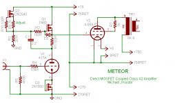
Fair enough, I am likely not up to speed on the terminology.My worst is, it can't be called a proper SE. Here is one example of proper SE attached:
What can you call it then, and would it be worth building?
Fair enough, I am likely not up to speed on the terminology.
What can you call it then, and would it be worth building?
First of all, I would consider output resistance of 6P15P non-linear, even though it is gorgeous tube. We discussed drivers of output stages with local parallel feedback extensively, search for Shade keyword. Linearizing KT-88 you force 6P15P (SV83) to distort.
First of all, I would consider output resistance of 6P15P non-linear, even though it is gorgeous tube. We discussed drivers of output stages with local parallel feedback extensively, search for Shade keyword. Linearizing KT-88 you force 6P15P (SV83) to distort.
What feedback would be suitable for this scheme to avoid distortion on the 6P15P?
Thanks Wavebourn, that was the keywords I needed. Doing my homework now... 😱
Interesting how many 'good' designs float around, which contains problems of different sorts. I didn't dig the triode driver out of nowhere... 😉
Interesting how many 'good' designs float around, which contains problems of different sorts. I didn't dig the triode driver out of nowhere... 😉
OK, that makes sense. I won't claim I have had time to read all, that has written on this subject, but I think I get the core issue.
So basically I need to convert the input stage to true pentode mode, including a properly stabilized screen grid supply, in order to get a good approximation for a CCSink. Only then will the Schade resistor and the anode load be able to work as a true (linear) voltage divider, which forms the core of the FB function.
This raises a few questions (which I may find the answers for through additional reading 😉 ):
*) Is the 6P15P(-EV) a reasonable choice for the pentode? I have a fair few of them, though I also have quite a few EL84 (~ 6P14P) and other common pentodes. Wouldn't mind finding something else at need, though I'd prefer to avoid 'exotics' if I can.
*) What kind of dynamic resistance would be considered acceptable? I suspect the trick is finding a suitably linear operating point for the pentode, coupled with high anode resistance. For the 6P15P it looks to my eyes like Vg2 = 200V, Vg1 = -7V, Ik = 10-15mA wouldn't be far off when combined with a suitable anode load (but I am mostly an RF guy, so what do I know? 😀 )
*) I noticed that you, Wavebourn, used cathode degradation on at least one of your pentode driver stages, for a LS-50 driver. Is that required for some particular reason, or was that just done to limit amplification? It was a 3 stage design with global feedback.
*) Any other showstoppers, or is the rest of my initial design close enough to keep polishing? I'd prefer to keep things simple for a start, Ie. no source/cathode followers and such, 'Powerdrive', unless required.
I had considered using gaseous voltage regulators to stabilize the screen supplies on the KT88s, but sort of dropped that idea again due to the large-ish values of quiescent current required to ensure the VR tubes didn't extinguish on current peaks from the screen grids. VR tubes may be an option for the driver stage though, much less overall change in current for 'reasonable' anode voltage excursions.
- Frank.
- Status
- Not open for further replies.
- Home
- Amplifiers
- Tubes / Valves
- The Russian Connection - (Maybe) A build thread. (KT88 SEP)