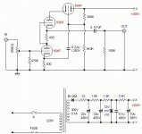
Why the 6SN7 attached to the power supply?
why even bother with something u see as junk?
Why the 6SN7 attached to the power supply?
Maybe some kind of current regulator... though wouldn't a pentode be the usual choice?
It's a mini regulator. Bogen used the same thing for their screen regulators on some amps. The SRRP suffers from poor power supply ripple rejection so it could be a useful application of the regulator.
Member
Joined 2009
Paid Member
Looks like a kind of active bootstrap current source - it takes a signal from the cathode of the lower tube and since the cathode resistor is not bypassed it samples the signal.
My guess is a bootstrap voltage source, in order to reduce distortion? It won't improve PSRR, but probably make it worse by directly injecting HT noise into the input cathode.
300V RMS AC half-wave rectified gives 420V, so plenty to drive a 330V zener chain.
300V RMS AC half-wave rectified gives 420V, so plenty to drive a 330V zener chain.
Odd! It does seem the lower 6SN7 is driving the upper one. But it's the opposite phase of a typical voltage bootstrap. It lowers the plate voltage on the middle 6SN7 plate when the signal is rising toward +. Since the effect would be small: 1/Mu, thru the plate, I can only guess this is some scheme for affecting distortion. Notice the same size cathode resistors on the lower two 6SN7's. Simulation needed. Could maybe replace the topmost 6SN7 with a Mosfet for convenience.
Why the 6SN7 attached to the power supply?
You really do not understand this circuit......
Why the 6SN7 attached to the power supply?
Hi They call it Felt 7,i have do one,very simple good sound compare to 12b4 pre .
You really do not understand this circuit......
Perhaps the designer didn't, as well. That seems to be common.🙁
You really do not understand this circuit......
can you enlighten us then please?
Yes, you are right. It's an anti-bootstrap!But it's the opposite phase of a typical voltage bootstrap.
Because of the high-pass nature of the 0.22uF and 430R, it will only send HT noise above about 1700Hz to the cathode. Is this a good thing?
Also, 300V half-wave rectified cannot possibly feed a 330V zener regulator 😉
Actually, half-wave rectified 300V can feed a 300V zener reg if the filter capacitors are large enough, it will have 50Hz ripple, though, but the peak value will again be approximately 400V. Much bigger problem: the net DC flux in the power transformer due to half-wave rectification!
The circuit itself seems like a cross between a regulator and... the fancy name escapes me, where the cathode bypass is not across the cathode resistor but rather to B+. Not going into it deeper, because there must be something quite odd with the rest of the circuit that it requires active filtering in addition to several RC stages after the rectifier, AND a zener regulator.
Yes, you are right. It's an anti-bootstrap!
Because of the high-pass nature of the 0.22uF and 430R, it will only send HT noise above about 1700Hz to the cathode. Is this a good thing?
That would be wrong as the other end of the capacitor goes to a high impedance point of the top triode grid and the divider network.
This circuit and variants of it seem to be cropping up in odd places, I've seen similar in some DI box designs as well.
I have not simulated it yet, but am getting curious so if I can find the time over the next day or so I may do it.
It is not something I would have ever thought of doing so I have no clue as to the rationale. Certainly the signal injected into the grid of the top 6SN7 is going to have a very subtle effect on circuit performance. I'd surmise it is intended to provide some distortion canceling, but I am probably far off base.
The one area I see that is clearly very poor design is the use of half wave rectification, a proper bridge would probably cost pennies more. Until I understand it I don't know whether the rest of it is also a poor design or some clever twist we've not encountered before.
Yes, you are right. I forgot to include the source impedance from the potential divider. I'm not having much success in understanding this circuit! Making silly mistakes does not help.That would be wrong
At low freqs the top triode gets a reasonable proportion of HT noise, plus some incoming audio, on its grid. At high freqs it gets very little HT noise, but still has audio. In between there will be phase shifts.
As kevinkr says, is this a very clever design or a very silly design? I suspect the latter, but I could be wrong.
Initial simulation results are very confusing to say the least.
The third triode on top apparently creates all sorts of interesting effects just by virtue of being there. A conventional SRPP simulates exactly as I would expect with a gain of roughly 20 - 22dB, the addition of that top triode leads to what appear to be to be entirely nonsensical effects on bandwidth, gain and phase response.
There has to be a problem with the triode model or the simulation to get the sort of results I am seeing - they are only possible if the impedance looking into the cathode of the upper triode increases by orders of magnitude with increasing frequency.
Edit: It's clear from the results that there has to be a problem with my simulation software (LTSpice IV) or the 6SN7 triode model I am using. I'll try a different triode model and see whether or not I have the same problem. SRPP works fine in simulations, this stage does not.
Edit2: It's the 6SN7 triode model I am using, just replaced with 5687 model and the results are much more in line with what I would expect. I'll have to go back and take a look at that model and see what is wrong with it.
Last edited:
Initial simulation results are very confusing to say the least.
I dont know anything about simulators, but I do know that a computer only knows what it has been tought and 'learned'
well, they are at the beginning of trying to devellop computers that 'teach' themselves, in relation to robotters, but its a very controversial subject
sorrey for the OT
- Status
- Not open for further replies.
- Home
- Amplifiers
- Tubes / Valves
- More junk from China