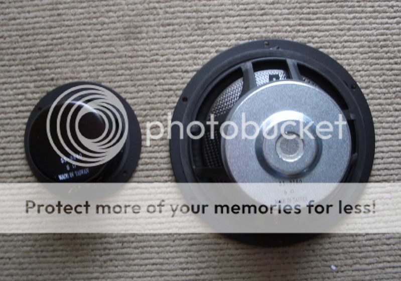
I have a full range open baffle driver which was originally a plain old woofer. I say used to be a woofer because I've modified it to sparkle a little, it was only 4 inches in diameter and went to 10-khz already so no big deal.
I'm stuck with the original metal + - tabs, would like to solder something on. I have as a temporary measure, screwed the copper alligator spring clips to the tabs and then open them up to insert the speaker wire but it is all sort of backwards from a typical situation one would expect.
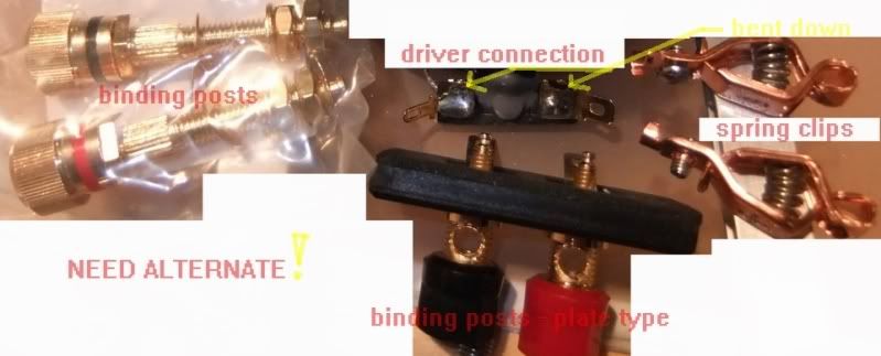
I see that real full range drivers have the posts terminals on the driver, this is what I would like to do.
Similar to goal-1:
Voxativ AC3 Fullrange Drive :: NEWS :: AboutHIFI
Similar to goal-2:
6moons showcase: Voxativ
Similar to goal-3:
http://www.diyaudio.com/forums/full-range/70204-bg-fullrange-driver-ether-6-a.html

1. What do I need to buy?
2. Do I have to mess with the lead wires or can I just tack on something to the existing tabs?
I'm stuck with the original metal + - tabs, would like to solder something on. I have as a temporary measure, screwed the copper alligator spring clips to the tabs and then open them up to insert the speaker wire but it is all sort of backwards from a typical situation one would expect.
I see that real full range drivers have the posts terminals on the driver, this is what I would like to do.
Similar to goal-1:
Voxativ AC3 Fullrange Drive :: NEWS :: AboutHIFI
Similar to goal-2:
6moons showcase: Voxativ
An externally hosted image should be here but it was not working when we last tested it.
An externally hosted image should be here but it was not working when we last tested it.
Similar to goal-3:
http://www.diyaudio.com/forums/full-range/70204-bg-fullrange-driver-ether-6-a.html
1. What do I need to buy?
2. Do I have to mess with the lead wires or can I just tack on something to the existing tabs?
Last edited:
You can modify a driver (woofer) as long as you are confident in your abilities and know what you are doing. But if you have a heavy or unsteady hand or are not good at soldering then you better leave the woofer as it is.
Why don't you attach some terminals/binding posts to the back of your open baffle? Why must a set of binding posts be affixed to the woofer? Can't you attach a set of binding posts to the back of your open baffle?
Why don't you attach some terminals/binding posts to the back of your open baffle? Why must a set of binding posts be affixed to the woofer? Can't you attach a set of binding posts to the back of your open baffle?
I've looked into that, but I'd rather avoid adding more solder joints, clips and jumper cables into the mix.Can't you attach a set of binding posts to the back of your open baffle?
I want to make this as simple and straightforward as possible - even if it means I have to think about what I'm doing.😀
Could I just solder these to the tabs?
https://www.madisound.com/store/index.php?cPath=404_119
An externally hosted image should be here but it was not working when we last tested it.
Sort of expensive, looking for cheap and simple.
EDIT: These are more my style ($2.40) , might be short enough too.
https://www.madisound.com/store/product_info.php?cPath=404_119&products_id=147
An externally hosted image should be here but it was not working when we last tested it.
EDIT-2:
Could this:
Replace me in Page Control under index.php
An externally hosted image should be here but it was not working when we last tested it.
Replace this?
Replace me in Page Control under index.php
An externally hosted image should be here but it was not working when we last tested it.
Last edited:
...I want to make this as simple and straightforward as possible - even if it means I have to think about what I'm doing...
Then just solder the speaker cable directly to the existing terminals. 😉
You could solder binding posts to the woofer tabs, but the tabs are not made for supporting additional hardware such as binding posts. Simple tabs bend quite easily, either that or the insulator/phenolic that the tabs are mounted to will bend and possibly break.
This is how I would do it, I'd desolder the tinsel lead wires, remove the original solder tab, then pop rivet on a new set of captive binding posts and resolder the tinsel lead wires.
This is how I would do it, I'd desolder the tinsel lead wires, remove the original solder tab, then pop rivet on a new set of captive binding posts and resolder the tinsel lead wires.
I've looked into that, but I'd rather avoid adding more solder joints, clips and jumper cables into the mix.
I want to make this as simple and straightforward as possible - even if it means I have to think about what I'm doing.😀
Could I just solder these to the tabs?
https://www.madisound.com/store/index.php?cPath=404_119
An externally hosted image should be here but it was not working when we last tested it.
Sort of expensive, looking for cheap and simple.
EDIT: These are more my style ($2.40) , might be short enough too.
https://www.madisound.com/store/product_info.php?cPath=404_119&products_id=147
An externally hosted image should be here but it was not working when we last tested it.
The factory tabs are designed for a Faston(Push on) terminal, or directly soldered to, not too much heat! The voice coil wires are not your typical hookup copper. Lots of cloth thread and extremely fine copper wires interweaved for flexibility, and very difficult to work with to ensure max connection of all conductors.
captive binding posts
Captive
This is Captive?
http://www.futurlec.com/Banana-Posts.shtml

These might work - short.
http://www.futurlec.com/Banana-Posts.shtml

A Plan?
Tinsel leads solder to the ends, then clamp the plates onto the stub where I cut the old tabs off of.
Dual Binding Post 1 Red 1 Black | Parts-Express.com
An externally hosted image should be here but it was not working when we last tested it.
An externally hosted image should be here but it was not working when we last tested it.
Last edited:
I don't understand why you'd want to add binding post to your drivers--why introduce even more metal into the equation?😕
Best, Don
Best, Don
Do you mean; metal near the magnet may cause magnetic interference?why introduce even more metal into the equation?
This particular driver is shielded, it's the small one on the left in the very first image at the top of this page.
I just cannot get over that something like what I'm looking for is not on the market already.
I don't like posts or clips at the speaker. Give me a good thin piece of metal to solder to.
dave
dave
Request for opinions:
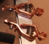
1. Compared to any and all of the binding posts so far posted, how do these spring clips rate against them as far as signal transfer and electrical conductivity?
2. Are they a serious consideration or option?
3. Aren't clips like these involved in every speaker driver measurement test because this is how they hook them up?
Attachments
Why not just solder the wire on the factory tab?
You mean solder the speaker wire right on the tabs?
That would be direct, but would not allow for ever changing the speaker wire.
That would be direct, but would not allow for ever changing the speaker wire.
I unsolder drivers all the time.
dave
I unsolder drivers all the time.
dave
Likewise.
I use 24ga wire internally. I form as small open loop on the end of the wire and tin it, puddle solder on the tab and then melt the wire into the puddle. This is not a mechanically secure as threading the wire through the hole in the loop and twisting the end of the wire over itself, but I have never has one fail. I can then unsolder the wire with very minimal heat.
Bob
I use a method similar to what Bob does. With the 24g solid i use internally, i actually usually snip the wire, so that i can put the driver on the bench to clean up the terminals.
dave
dave
24ga is tiny, why so small?
How much power do you expect to supply to your drivers? Most of the drivers discussed here will never see more than 10w. What kind of voltage drop do you expect in say 6ft of 24ga wire? And how much less voltage drop do you need?
Bob
Looking at the wires connecting a crossover to the woofer and tweeter of an old Infinity speaker I have taken apart for another project, I see that it is rather small compared to a common 16-ga braided speaker wire.
I take it that it is because the run is so short that the solid wire can be 24-ga.
I'm new at this, I'm still thinking in long run speaker wire terms. I do have some color coded solid automotive wire somewhere. I'll take a look at that. Should be a lot easier to solder than fat braided stuff.
To answer the question, 25w max. to 50w peak (estimate).
Last edited:
- Status
- Not open for further replies.
- Home
- Loudspeakers
- Full Range
- Binding Posts on FR OB