Hi,
If you are planning on doing the 5ohm degeneration trick you need:
1) N-P matched mosfets for each channel.
2) 2SJ74 with an Idss about 1mA more than 2SK170
3) either add 5ohm resistor between the 2SJ74 source pin and the feedback node, or replace R with 15ohm and feedback of 75ohm.
All three steps are required.
I built a single ended F5 as above with one pair of Toshibas. I set the bias level much lower than irfs as I was not sure what is the recommended bias level. Any recommendations on what should be the bias level with Toshibas? My power rail is standard 24v.
Thanks.
Thanks for the responses.
I adjusted P1 almost fully upwards without any voltage reading across the source resistor; P2 slowly raised the voltage upwards. The right channel when connected with the left disconnected blew the fuse.
That is a sure way to burn the circuit - good thing you were saved by the fuse. Follow Zen Mods instructions and you'll get it right.
I built a single ended F5 as above with one pair of Toshibas. I set the bias level much lower than irfs as I was not sure what is the recommended bias level. Any recommendations on what should be the bias level with Toshibas? My power rail is standard 24v.
Same as IRF
that's the correct formula.Just to clarify, I am asking if a 1uf mkp is a good capacitor value to block dc input to the f5. I am assuming 101k as the 'R' value of the input. I am not sure if 1/(2*pi*r*c) is the right way to calculate the high pass frequency for this setup.
TIA.
I think 101k is the input impedance.
If you use 1uF (not 1uf) and 101k then F-3dB should be ~1.6Hz
The F-1dB should be ~3Hz. This allows the DC coupled amplifier to reproduce all the audio signal from 20Hz and up.
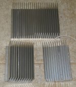
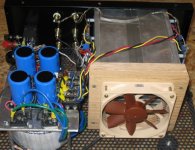
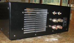
F5 cooling borrowing from Hafler DH500
Here is my new stereo F5 build, using a single HeatSinkUSA E007, cut in half and reassembled to make a heat tunnel. Airflow is provided by a Noctua NF-S12-B fan shown in the images. With this arrangement the heatsink temperature rise is only 30 degrees F (17C) with 12 volts to the fan. The MOSFETS are mounted with 1 mil thick mica and Thermalcote.
Since these fans are so quiet, especially at lower RPMs, it seems obvious to me that higher wattage class A designs should take advantage to the 3X increase of wattage for the same heatsink by using airflow from a quiet fans.
BTW: With the addition of some insulated mountings, the 2 heatsinks can be electrically isolated from each other and ground, if you are inclined to mount your MOSFETS without any insulators.
Attachments
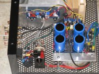
Extra connections for bias adjustment
After smoking one of my F5 channels while performing bias adjustments, I decided to add some additional connections to the cviller PCB to make it easier and safer to make the adjustments. For each channel, five wires of a CAT5 cable were connected to the ends of R11, R12, and the output, each thru a 1k ohm resistor to minimize any effects do to the wiring. A 6th CAT5 wire is connected to ground. The 6 pairs from the two CAT5 cables are connected to a 2 pole x 6 position rotory switch whose 2 outputs are connected to a multimeter for bias adjustment.
After smoking one of my F5 channels while performing bias adjustments, I decided to add some additional connections to the cviller PCB to make it easier and safer to make the adjustments. For each channel, five wires of a CAT5 cable were connected to the ends of R11, R12, and the output, each thru a 1k ohm resistor to minimize any effects do to the wiring. A 6th CAT5 wire is connected to ground. The 6 pairs from the two CAT5 cables are connected to a 2 pole x 6 position rotory switch whose 2 outputs are connected to a multimeter for bias adjustment.
Attachments
F5 listening impressions
The last amp I built was a Hafler DH500 (250W/channel) in about 1986). I have loved its sound until I finished my Pass F5 yesterday and started to hear the differences. The DH500 at 1 watt listening levels is probably at its worst operating level for crossover distortion. The F5 definitely sounds more transparent, especially at the higher frequencies, where Miles Davis's Will O' the Wisp in Sketches of Spain could be very innoying.
One surprise was that low frequency (bass) output of the F5 appears to be higher than from the DH500. Hard to explain. Is this a damping factor issue?.
The F5 is DC coupled.One surprise was that low frequency (bass) output of the F5 appears to be higher than from the DH500. Hard to explain. Is this a damping factor issue?.
You have effectively removed two high pass filters from your system. You are now hearing the difference between a very slightly rolled off bass with a medium rolled off bass. And this with the same speakers that cannot reproduce those very low bass frequencies.
Aaargh; frustration riegns !. I think I must be one step back from a caveman. Connected up the right channel of my F5 first through the bulb and then without. This time the fuse did not blow. Again as per the left side adjusting P1 does not result in any voltage reading across the source resistor nor on the output whereas P2 I get an increase in mv reading across the output but no reading on the source resistor?? The amp has been powered up for 30 mins without the fuse blowing and no smoke. I connected the left channel, fuse did not blow but niether trimmer makes any adjustment.🙁
measure the voltage across the trimmer.
this voltage should change as you adjust the trimmer.
The group of resistors pass a current to the jFET.
This is nearly a constant current.
If the trimmer is set to 0r0 then Vrt=0v0
If the trimmer is set to 10r and 8mA flows to the jFET then Vrt~80mVdc ~0.080Vdc
Check the voltages across all the trimmers.
Check the voltages across the jFET source resistors.
Mark these on a schematic and post a pic of the marked up schematic.
Thanks Andrew will do when I can use my workbench [dining table]. The wifes sorting Avon at the moment.
you live dangerously !
A friend asked me to build an engine for him.
He presented me with his workshop: The kitchen worktop !!!
and his wife was in at the time.
A friend asked me to build an engine for him.
He presented me with his workshop: The kitchen worktop !!!
and his wife was in at the time.
Brave; not really. After my undergoing heart surgery 2yrs ago Elizabeth is just happy to see me building things again. Not that I'm recommending that as a means to get round the wife to let you use the dining room as a workshop you understand😀
Great assembling! Silent fans are a great way to achieve big amounts of power in an small confined space. People don't really realize how silent can a fan be if it is well designed and running at low RPM. Truly inaudible with your ear further than 30cm.Here is my new stereo F5 build, using a single HeatSinkUSA E007, cut in half and reassembled to make a heat tunnel. Airflow is provided by a Noctua NF-S12-B fan shown in the images. With this arrangement the heatsink temperature rise is only 30 degrees F (17C) with 12 volts to the fan. The MOSFETS are mounted with 1 mil thick mica and Thermalcote.
Since these fans are so quiet, especially at lower RPMs, it seems obvious to me that higher wattage class A designs should take advantage to the 3X increase of wattage for the same heatsink by using airflow from a quiet fans.
BTW: With the addition of some insulated mountings, the 2 heatsinks can be electrically isolated from each other and ground, if you are inclined to mount your MOSFETS without any insulators.
Hi,
is a DC motor fan just as quiet if the reduced speed supply is PWM (pulse width modulated) rather than reduced voltage?
I saw a circuit based on a 555 that provided variable speed by changing the duty cycle as the sink temperature changed. All that switching must create electrical interference, but does it also cause mechanical vibration in the motor and/or fan blades to make noise worse?
Hello,
I have problem with F5 amp. When I set P1, P2 voltage to 4.2V, across R11, R12 shows 0,15V (must be 0,6V). The amp is working.
When I increase P1, P2 to 4,8V, across R11, R12 shows 0,55V, but now an amp works with a low level signal. If I Increase a signal, amp is “closing”, and it begin to heat at Q3,Q4. After several tries, the 2sk170 were “killed”. I changed it. but I killed it also.
I put 2sk170bl and 2sj74bl.
Please help.
Hi everyone,
I plan to finalyse my BoM and then purchase the last little things I need.
Nevertheless, I have 2 questions about 1) the transformer 2) the case.
I plan to finalyse my BoM and then purchase the last little things I need.
Nevertheless, I have 2 questions about 1) the transformer 2) the case.
- according to several threads on several forums I read, it seems that a 400VA instead of a 300VA would be better. Is that true?
- I plan to buy either a HiFi2000 4U 300mm or a 4U 400mm. According to the attached file, a 4U 300mm should be ok, but isn't it a little bit too tight?
Attachments
Hi everyone,
I plan to finalyse my BoM and then purchase the last little things I need.
Nevertheless, I have 2 questions about 1) the transformer 2) the case.
Thank you very much in advance.
- according to several threads on several forums I read, it seems that a 400VA instead of a 300VA would be better. Is that true?
- I plan to buy either a HiFi2000 4U 300mm or a 4U 400mm. According to the attached file, a 4U 300mm should be ok, but isn't it a little bit too tight?
1. for stereo build, 400VA would be better, for mono amps 2x 300VA equally good
2. stick to 300mm, and 5U being the best choise
boards are small, so 300mm should be fine
just place your trafo close to front plate, maybe preferably in upright position
just place your trafo close to front plate, maybe preferably in upright position
Just make sure the trafo bolt does touch the top of the chassis as well or you will have a shorted turn.
1. for stereo build, 400VA would be better, for mono amps 2x 300VA equally good
Ok, then 400 VA it is/
2. stick to 300mm, and 5U being the best choise
boards are small, so 300mm should be fine
just place your trafo close to front plate, maybe preferably in upright position
Hmm, actually, I was first thinking about taking a 4U 400mm. Hence, I saw that 4U 300mm would be ok, which would save me about 40 euros... 5U is too expensive for me. Is the latter is not too tight, I'll take it but I'm not so sure...
- Home
- Amplifiers
- Pass Labs
- F5 power amplifier