Hi, I am building an audio amplifier and the case really needs a decent front panel which I have designed but can not find any method other than to silk screen. Back in the 1970’s Radio Spares starting doing a kit for this sort of thing, which you put your artwork under the UV light box and then washed it off with the supplied chemical and it really looked good. Does anybody know where I could find this again? - TC
I remember years ago I bought a transparent adhesive vinyl sheet with audio white text printed on it, aux, volume, tuner, power, amplifier...etc. You just neatly cut out the required text for the audio equipment and stick it on. They were great. Not sure if you can still get them?
Here are a couple of other options for getting a fancy front panel.
1. Look up DIY anodizing on the net. If you have an UNanodized plate, coat with photoresist, expose and develop. Drop the panel into the anodizing bath and you can have any color you want.
2. Go to the Arts/Graphics store and look at their selection of screenprint materials. Many years ago, I did 2 color T-shirts with materials from the local Art store. They even make a photo sensitive sheet that is applied to the screen and the screen is then exposed and developed.
3. Try your local sign shop and get them to cut your design onto a piece of vinyl. Lay the vinyl down on your plate and remove the bits that you want to be labels. Burnish the vinyl edges and then either
a. etch the open areas
b. fill the open areas with paint
Good luck on whichever way you decide to go, and keep us posted.
Dr. Spiff

Hi Andrew,
Any idea how this panel was made (and where to get the supplies for it)? 😉
Cheers,
Mark.
Hi Andrew,
Any idea how this panel was made (and where to get the supplies for it)? 😉
Cheers,
Mark.
An externally hosted image should be here but it was not working when we last tested it.
An externally hosted image should be here but it was not working when we last tested it.
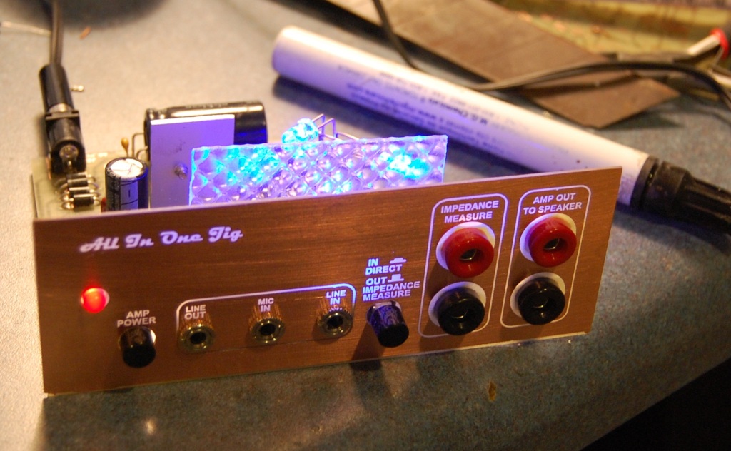
This kind of illuminated front panel is fairly easy to make. The basic requirement is a sheet of clear plastic and some LEDs arranged to fire into the sheet along the thin faces, just like (!) the illumination sheet in an LDC monitor. I used ultrabright side-firing LEDs accommodated in laser-cut slots in the sheet, these were carried on a custom PCB.
The lower picture shows a rear view of the illuminated laser-cut pits on a prototype in test.
The sheet is abraded behind the areas where light is required to be thrown forward. For my first experiments I used a piece of veroboard held against the clear sheet and blasted it with a sandblaster. Later I had access to a laser cutter which I would use to make a load of shallow pits. These pick up the side-fired light and throw it out at right-angles to provide a bright glow where required. Usually a bit of experimentation is required to get the result to come out even.
Lastly you need an opaque mask to create the graphics and lettering. This can be done by painting a clear sheet on one side and laser etching the required pattern or CNC engraving a thin aluminium sheet, or just printing a transparency on a laser printer and incorporating it in a sandwitch of sheets.
As for supplies, bust open a dead LCD monitor or laptop to get started.
I hope you can understand how this works from this somewhat long-winded description. Any queries, ask again...
w
Last edited:
Front Panel Express: Custom Front Panels with free Front Panel Designer
If you don't have a laser cutter and etcher.
If you don't have a laser cutter and etcher.
I've used this kind of stuff and it works great. Because it has whole electronics-related words (like "Volume") you don't have to stress over aligning the individual letters. I got mine from Ocean State Electronics, but it looks like they are out of business, and I can't vouch directly for this store:
Unicorn Electronics - White Audio, TV & Hi-Fi Dry Transfer Lettering AUD-1W
Unicorn Electronics - White Audio, TV & Hi-Fi Dry Transfer Lettering AUD-1W
Front Panel Designer. Free software and excellent product. I made the toplate for my Aikido with anodized and infilled lettering. Looks great.
reviving thread....
A couple of years ago I bought some decal sheets but just got around to using them this week.
Supplier was lazertran as I recall.
Sheets are 8.5 x 11 inches, so best for smaller projects.
Printed on a newer Samsung Laser printer (SCX-4600) and 'set' the print with a heat gun (hot-air gun), since the newer printers don't heat the copies very much.
The decal is a water-type, with fairly thick plastic compared to my recollection of the decals I used on plastic models as a kid.
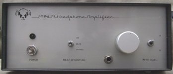
For this project (Panda headphone amp), I printed a mirror image of the graphics on the decal material. When transferred to the faceplate, the 'printing' is under the plastic sheet. Then, I followed the lazertan instructions and baked/melted the plastic on to the faceplate- basically you heat the plate in the (kitchen) oven over a number of hours, gradually raising the temp from 150F to about 350-375F.
Faceplate was aluminum, primed and painted, and 'baked' in the oven to 'cure' the paint. The decal was applied and baked. One nice thing is that the decal melts where the holes are drilled in the faceplate, so no worries about cutting them later.
John
A couple of years ago I bought some decal sheets but just got around to using them this week.
Supplier was lazertran as I recall.
Sheets are 8.5 x 11 inches, so best for smaller projects.
Printed on a newer Samsung Laser printer (SCX-4600) and 'set' the print with a heat gun (hot-air gun), since the newer printers don't heat the copies very much.
The decal is a water-type, with fairly thick plastic compared to my recollection of the decals I used on plastic models as a kid.
For this project (Panda headphone amp), I printed a mirror image of the graphics on the decal material. When transferred to the faceplate, the 'printing' is under the plastic sheet. Then, I followed the lazertan instructions and baked/melted the plastic on to the faceplate- basically you heat the plate in the (kitchen) oven over a number of hours, gradually raising the temp from 150F to about 350-375F.
Faceplate was aluminum, primed and painted, and 'baked' in the oven to 'cure' the paint. The decal was applied and baked. One nice thing is that the decal melts where the holes are drilled in the faceplate, so no worries about cutting them later.
John
Attachments
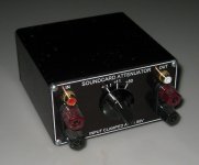
Another technique I've used is printing a reversed image on to 8.5 x 11 'overhead' transparency stock (or having a commercial shop do it on to 16 x 20 transparent stock, from my file).
Then spray paint over the printing, which you can read through the clear plastic.
Sandwich the transparency between the metal faceplate and a thin plexi/lexan cover plate. The mounted controls secure the plexi.
Sort of 'Marshall amp style'.
John
Then spray paint over the printing, which you can read through the clear plastic.
Sandwich the transparency between the metal faceplate and a thin plexi/lexan cover plate. The mounted controls secure the plexi.
Sort of 'Marshall amp style'.
John
VictoriaGuy, you scored victory! Thank you for sharing. If I understand correctly, the entire face has decal coating on it?
Cheers!
Cheers!
Last edited:
Not to judge but the Panda logo and Title seems to tilt slightly down to the right? Could be fish-eye effect from camera image? Top notch regardless!
Last edited:
Thanks!VictoriaGuy, you scored victory! Thank you for sharing. If I understand correctly, the entire face has decal coating on it?
Cheers!
Yes- decal covers entire face.
For a larger project, I suppose you could use cut pieces, but it would be difficult to get the face to look completely smooth, even with lacquer overspray, I think.
John
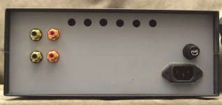
Hey Victoria, I hope you do the back panel too! I love DIY that looks like factory built or better! There are people out there making custom-ish equipment for Hi-Fi that looks simply terrible. Often, in my opinion, the boutique custom gear looks like junk. Not all of it of course, but some of it.
Now I must go research this "Panda" and see what it is all about... a dude won't invest that kinda time unless he's happy with it...must be good?
Now I must go research this "Panda" and see what it is all about... a dude won't invest that kinda time unless he's happy with it...must be good?
Well, I only make your standard to the 50% level, I'm afraid!😀Hey Victoria, I hope you do the back panel too! I love DIY that looks like factory built or better! There are people out there making custom-ish equipment for Hi-Fi that looks simply terrible. Often, in my opinion, the boutique custom gear looks like junk. Not all of it of course, but some of it.
It's an excellent-sounding HP amp. 'Kit' has good components but no instructions. PCB is excellent-well labelled. Kits from hifidiyaudio....not cheap, but not outrageous at all, considering what you get. Complete kit with case and transformer is $200+ shipping. I built mine from the $100 PCB+components kit (no transformer or case).Now I must go research this "Panda" and see what it is all about... a dude won't invest that kinda time unless he's happy with it...must be good?
Hop on over to RockGrotto and you'll find lots of info.
Rock Grotto Audio Forum - For Headphones - Headphone Amps - Amplifiers - X-Can V2 - Musical Fidelity - headphone Discussion - Amplifier Discussion - DIY - Amplifier Kits - Projects - SCHA - Sennheiser - Beyer - Grado - Audio Technica - Headphone amp
Rock Grotto Audio Forum - For Headphones - Headphone Amps - Amplifiers - X-Can V2 - Musical Fidelity - headphone Discussion - Amplifier Discussion - DIY - Amplifier Kits - Projects - SCHA - Sennheiser - Beyer - Grado - Audio Technica - Headphone amp
John
Attachments
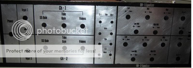
A technique that I have used with good results on an aluminum panel was to etch it, anodize and dye and then fill. It is quite a bit more work then using dry transfer lettering. The photo shows my first (and only) attempt. Here is what I did:
1) Lay out your front panel design using the layout/drawing program of your choice.
2) Print the image using an inkjet printer on a good quality inkjet transparency film. I am now using AccuBlack and AccuArt. http://www.ikonicsimaging.com/downloads/Accu_Art_filmSpecial_080501.pdfThese films seem to provide dense blacks when I print on the photo setting on my inkjet. I use these for making PC boards also.
3) Laminate a clean aluminum panel with the photoresist film available from Micromark http://www.micromark.com/Photo-Resist-12-X-19-Pkg-Of-2,8354.html . (I use a GBC laminator). Keep in mind that this is a negative resist, so that wherever you lay down a black line in your image will be washed away when you develop it.
4) Expose under a UV light source.
5) Develop the panel. I highly recommend that you do not use sodium hydroxide to develop this film, despite Micromark’s recommendation. Ordinary washing soda (sodium carbonate-Arm and Hammer brand is cheap and easy to get) works much, much better. Use about 1 tsp per quart. I brushed very lightly with a foam brush to encourage development.
6) After developing, rinse thoroughly, allow it to dry and harden.
7) Etch using the salt etching solution described here: Salt etch web . This is very similar to etching PC boards. Hint: Saniflush no longer seems to use sodium bisulfate as its active ingredient, but you can purchase sodium bisulfate at pool supply/spa stores. It seems to be used in spas. Copper sulfate is available in home supply and hardware stores since it is used to kill roots in drain pipes. This etching solution is reasonably safe and won’t attack the photoresist. Again I brushed lightly with a foam brush to remove the copper colored material that appears at the etching sites. Watch for undercutting.
8) After etching to a suitable depth, remove the photoresist. Sodium hydroxide works for this but I simply wipe on a bit of acetone since sodium hydroxide also etches aluminum and might ruin the finish that you want..
9) Next anodize and dye (if you wish) using your favorite anodizing setup.
10) Fill the etched lines with a contrasting color acrylic (or other filler of your choice). I used an artist’s acrylic. This took a bit of effort. First, I spread some acrylic on the panel, removed most of the excess with a little squeegee, let it dry almost completely, and then polished off the remaining excess with a slightly dampened, soft cloth. I had to do this twice to get good results. I had also tried first filling the etched lines, then sanding flush after the acrylic dried (so far so good), then anodizing, sealing and dyeing. THIS DID NOT WORK since the acrylic was stained by the anodizing dye.
This process involves some effort and investment, but I used a lot of the same equipment that I was already using for printed circuit work (the laminator and UV exposure stand) and the anodizing set up for cases so the incremental investment on my part was small. This was a proof of concept for me, but the result was pretty good, I think and was worth the effort; I will be using the process again.
Terry
Attachments
Last edited:
- Home
- Amplifiers
- Solid State
- DIY amps front panel lettering