Are the PCB's for the KSA or the tube preamp offered for sale? If so how much?
RG
I suggest emailing Abin. He is around and is responding quickly.
The design looks great. When do you expect the parts ?
fs
I'm hoping around middle net week. Can't wait!
hi abin,
Very nice work, abin can you share pcb files of tube pre amp, and ksa 50 so ican etch my own files.
i iam from india, And i have had very bad experiences with post ,last time i brought some goods off ebay china, i didnt recieve it.
Good day
Very nice work, abin can you share pcb files of tube pre amp, and ksa 50 so ican etch my own files.
i iam from india, And i have had very bad experiences with post ,last time i brought some goods off ebay china, i didnt recieve it.
Good day
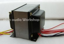
After a long time i started with my build again.
At the speed I am going currently it should be done within the next week or so.
This weekend was spent getting my lm555 relay delay start circuit and fan supply running. Also got everything attached to Alu and mounted on top of the toroidals.
Others parts on that board is the vu meter driver circuit.
Attachments
-
![2011-01-22 19.09.15 [1024x768].jpg](/community/data/attachments/200/200262-3d36e5c13c2be3af84958b44b7ca66ca.jpg?hash=PTblwTwr46) 2011-01-22 19.09.15 [1024x768].jpg130.1 KB · Views: 464
2011-01-22 19.09.15 [1024x768].jpg130.1 KB · Views: 464 -
![2011-01-22 19.09.32 [1024x768].jpg](/community/data/attachments/200/200268-672b339688bd671c32913d6cf0b636b9.jpg?hash=Zyszloi9Zx) 2011-01-22 19.09.32 [1024x768].jpg107.7 KB · Views: 449
2011-01-22 19.09.32 [1024x768].jpg107.7 KB · Views: 449 -
![2011-01-22 19.09.44 [1024x768].jpg](/community/data/attachments/200/200275-6048b6320dd1f1a5a1259bf90062c3bd.jpg?hash=YEi2Mg3R8a) 2011-01-22 19.09.44 [1024x768].jpg100.2 KB · Views: 417
2011-01-22 19.09.44 [1024x768].jpg100.2 KB · Views: 417 -
![2011-01-23 21.17.35 [1024x768].jpg](/community/data/attachments/200/200298-9f246316fba4fd02991aad6430aff734.jpg?hash=nyRjFvuk_Q) 2011-01-23 21.17.35 [1024x768].jpg132.4 KB · Views: 205
2011-01-23 21.17.35 [1024x768].jpg132.4 KB · Views: 205 -
![2011-01-22 19.09.54 [1024x768].jpg](/community/data/attachments/200/200288-a2b0826a9c5b3c3d49b6bb8ed63022df.jpg?hash=orCCapxbPD) 2011-01-22 19.09.54 [1024x768].jpg134.5 KB · Views: 223
2011-01-22 19.09.54 [1024x768].jpg134.5 KB · Views: 223 -
![2011-01-23 21.17.07 [1024x768].jpg](/community/data/attachments/200/200294-e895df18745bf91856df8e4a4cdfb0d6.jpg?hash=6JXfGHRb-R) 2011-01-23 21.17.07 [1024x768].jpg174.2 KB · Views: 239
2011-01-23 21.17.07 [1024x768].jpg174.2 KB · Views: 239 -
![2011-01-23 21.17.17 [1024x768].jpg](/community/data/attachments/200/200305-1ec41058df91f9c3aeebd05657f27bc3.jpg?hash=HsQQWN-R-c) 2011-01-23 21.17.17 [1024x768].jpg144 KB · Views: 200
2011-01-23 21.17.17 [1024x768].jpg144 KB · Views: 200
Nice..
I'm not a fan of the VU meters (PERSONAL opinion) but LOVE the execution of the fan with channeled cooling over the heat sinks.
I'm not a fan of the VU meters (PERSONAL opinion) but LOVE the execution of the fan with channeled cooling over the heat sinks.
Nice..
I'm not a fan of the VU meters (PERSONAL opinion)
In hindsight they are a bit small for the enclosure. I should have seen it while doing the drawing ,but oh well. It'll do...
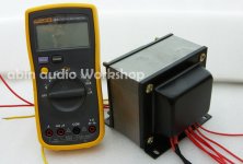
Did lots of wiring over the weekend.
I also powered it up after double checking my wiring 10000 times. all was well. I am not 100% sure how long to leave the 50ohm 20W resistors in series with the 500va transformers primary in circuit. I currently have it on roughly 2 seconds. They go up to about 55C in those 2 seconds. I suppose best way will be to put oscilloscope on output rails and see voltage ramps and decide then how long it should wait before shorting out.
I forgot to buy panel mount rca's so after work today further testing will commence and some resistive loads. I also want to run it for a few hours to see what temp the heatsinks get and how fast fan must turn and how high bias can be.
don't you hate it when you have a nice simple enclosure with all the parts and then you have to clutter it up with wiring!!!. I have to confess though that my wiring isn't the neatest. 😛
I also powered it up after double checking my wiring 10000 times. all was well. I am not 100% sure how long to leave the 50ohm 20W resistors in series with the 500va transformers primary in circuit. I currently have it on roughly 2 seconds. They go up to about 55C in those 2 seconds. I suppose best way will be to put oscilloscope on output rails and see voltage ramps and decide then how long it should wait before shorting out.
I forgot to buy panel mount rca's so after work today further testing will commence and some resistive loads. I also want to run it for a few hours to see what temp the heatsinks get and how fast fan must turn and how high bias can be.
An externally hosted image should be here but it was not working when we last tested it.
don't you hate it when you have a nice simple enclosure with all the parts and then you have to clutter it up with wiring!!!. I have to confess though that my wiring isn't the neatest. 😛
Last edited:
I cannot see many twisted pairs !
All the flow and return pairs (or triplets) should be twisted.
A resistor based soft start should be bypassed in under 500ms and preferably between 100ms and 300ms.
An NTC based soft start can be bypassed as quickly as the resistor type, but it does no harm to leave it unbypassed for 2s.
All the flow and return pairs (or triplets) should be twisted.
A resistor based soft start should be bypassed in under 500ms and preferably between 100ms and 300ms.
An NTC based soft start can be bypassed as quickly as the resistor type, but it does no harm to leave it unbypassed for 2s.
The +-VCC is not twisted , i felt that the path between the capacitors and pc board is so short that it won't make a difference/practical.
But looking at it now I can twist at least a part of the circuit. Easy enough to unscrew and twist as well as possible.
The speaker ground wire and + wire I can easily loosen and twist together.
But looking at it now I can twist at least a part of the circuit. Easy enough to unscrew and twist as well as possible.
The speaker ground wire and + wire I can easily loosen and twist together.
There are lots of single cables/wires passing all over.
These single wires must be part of a circuit. Where is the flow/return partner to each of these?
These single wires must be part of a circuit. Where is the flow/return partner to each of these?
HI!
Everybody is good!
Because has been busy with the work, has no free time to access the net, recently I also planned that redesign KSA50, heavy has come again,i want to design each channel to be independent.PCB similarly free and everybody share.
Everybody is good!
Because has been busy with the work, has no free time to access the net, recently I also planned that redesign KSA50, heavy has come again,i want to design each channel to be independent.PCB similarly free and everybody share.
How about 22.1ohm instead of R127 & R128 of 25ohm?
Hello Mr. KSA50s across the world,
As asked in the title above, is there any problem when R127 & R128 are changed from 25ohm to 22.1ohm? I'm planning to diy my own 25~30W KSA amp enclosed with a miniture pre-amp.
Thx in advance.
Hello Mr. KSA50s across the world,
As asked in the title above, is there any problem when R127 & R128 are changed from 25ohm to 22.1ohm? I'm planning to diy my own 25~30W KSA amp enclosed with a miniture pre-amp.
Thx in advance.
Hi all,first post on this thread. I started to build a lower power version of the KSA50 with 24V rails about two years ago but due to personal circumstances had to abandon the project. I am now in a position to start again but have forgotton some things.
ANDREW T you kindly helped me before with component values around the long tailed pair for 24V operation, I have another question if you or anyone else can help.
I know the output transistor emitter resistors are 0.5 ohm, I have a stock of 1ohm and 0.1ohm non inductive resistors, could I use either of these values in stead of 0.5 ohm.I am using a pair of 15003 and 15004 per channel.
The heatsinks I am using are approx 400x150x40 per channel non fan assisted, do you consider they will be OK, I hope to run at about 1.6A per channel bias to achieve 25Watt
I hope you don't mind these questions but I have posted on the original KSA thread but have not recieved any replies, perhaps it has gone cold.
Thanks for your help
Alan.
Just discovered this thread after finding a scaled down KSA50 kit online. I was a much younger man the first time i heard a KSA %) and i have always been impressed with the quality of the famous Krell inside and out. I would very much like to build one of these magnificent beasts as close to the original as possible. (or over build 😉 ) I have seen a variety of PCB available on EBAY and unfortunately as many of you are aware there is very little information available on the original KSA50 to study. I am indeed envious of the fellow who got the burnt up KSA50 I'd do just about anything for the information inside that blackened box. 😀 Anyway, in short any information including sources for parts, specifications, chassis etc would be more than welcomed as it seems that building your own is most likely the only way to get your hands on one of these wonderful amplifiers. Thank you in advance everyone.
You will get everything you need in this thread😉
http://www.diyaudio.com/forums/solid-state/31077-krell-ksa-50-pcb.html
http://www.diyaudio.com/forums/solid-state/31077-krell-ksa-50-pcb.html
I had hoped to streamline things a bit instead of reading over 800 pages of largely outdated information but, i guess no pain no gain lol. I better get reading since i'm sure i will be reading it all many times over anyway 😀
gxcnabin,
I'm interested in the chassis, did you get around to pricing them and are they still available ...
Regards,
I'm interested in the chassis, did you get around to pricing them and are they still available ...
Regards,
After reading huge portions of the other thread I am still a little confused on several issues. What were the original output devices? Are any of the PCB's available accurate for a real clone buile or simply the same circuit modified for a rainbow of available parts? What PCB is best? Highest quality? what of power supply pcb's, transformers etc? I am on a mission to have a KSA50 and really have no interest in modifying one of the best audio amplifiers ever as that would seem to defeat the purpose of cloning one. I used to build HF amplifiers so I know how easy it is to start tweaking a design. In this case though it seems everyone starts out building a classic Rolls and ends up adding A/C, tinted windows etc until it is only vaguely resembles what it once was intended to be. Also some of the 'facts' presented seem to be very.....flexible. One post regarding transformers states 'factory' ratings for the original Krell and follows up saying one would need more transformer for low impedance loads. This makes no sense to me since driving insanely low impedance loads was one of the KSA50's great strengths. As always thank you for the help in advance. 😀
your conclusion makes no sense to me.One post regarding transformers states 'factory' ratings for the original Krell and follows up saying one would need more transformer for low impedance loads. This makes no sense to me since driving insanely low impedance loads was one of the KSA50's great strengths. As always thank you for the help in advance. 😀
The kas50 has a 2pair output stage and, if I recall correctly a 500VA transformer.
That to me, suggests it is good for 4ohm speakers and a 2r0 resistor load. That in my view is certainly not in the ball park of insanely low impedance loads.
- Status
- Not open for further replies.
- Home
- Amplifiers
- Solid State
- KSA50 AMP(New production Live in...)