Hi guys!
I know there are tons of threads about the LM317 regulator, but it's really hard to find particular things with the search function, because the LM317 is mentioned in almost every thread in this forum! 🙂
Anyway, I would like to build two small PSUs with the LM317 for powering a DACs analogue stage and its digital stage. I wonder what would be the best solution, since the sonic differences between everything I tried until now are not that easy to discern.
I surfed the web a bit, and what I came up with is a bit of a mixture between all the things mentioned on these two sites:
Using 3-pin regulators off-piste: part 1
High End Audio - LM317
Input voltage would be 15VAC, output voltage should be ~18V.
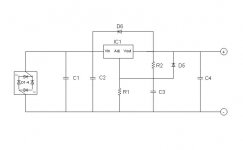
Now, this would be my suggested choice of components:
D1-4: Shottky BYV2100, 2A/100V (low forward voltage drop, soft recovery)
D5, D6: 1N4002 (protection diodes, for safety reasons)
C1: 470uF-1000uF/35V (electro, low-ESR, Elna Silmic or Panasonic FM)
C2: 0,1uF/63V (film, Wima MKS2)
C3: 10uF-22uF/35V (electro, no specific type, or tantalum)
C4: 1uF-10uF/35V (electro, non-low-ESR!)
R1, R2: (according to desired Vout, here: 3k3, 240R)
What do you think about this component choice and circuit layout?
Perhaps some of you have already heard different LM317 configurations?
Thanks a lot!
Martin
I know there are tons of threads about the LM317 regulator, but it's really hard to find particular things with the search function, because the LM317 is mentioned in almost every thread in this forum! 🙂
Anyway, I would like to build two small PSUs with the LM317 for powering a DACs analogue stage and its digital stage. I wonder what would be the best solution, since the sonic differences between everything I tried until now are not that easy to discern.
I surfed the web a bit, and what I came up with is a bit of a mixture between all the things mentioned on these two sites:
Using 3-pin regulators off-piste: part 1
High End Audio - LM317
Input voltage would be 15VAC, output voltage should be ~18V.
Now, this would be my suggested choice of components:
D1-4: Shottky BYV2100, 2A/100V (low forward voltage drop, soft recovery)
D5, D6: 1N4002 (protection diodes, for safety reasons)
C1: 470uF-1000uF/35V (electro, low-ESR, Elna Silmic or Panasonic FM)
C2: 0,1uF/63V (film, Wima MKS2)
C3: 10uF-22uF/35V (electro, no specific type, or tantalum)
C4: 1uF-10uF/35V (electro, non-low-ESR!)
R1, R2: (according to desired Vout, here: 3k3, 240R)
What do you think about this component choice and circuit layout?
Perhaps some of you have already heard different LM317 configurations?
Thanks a lot!
Martin
Attachments
Last edited:
When I do power supplies, I'll always add passive RC on the input to the reg. Reason being their ripple rejection gets really poor above the audio band so they need a helping hand to stay clean above 100kHz. On your schematic, that means adding an R in the positive line between C1 and C2. I also go for a fairly big output cap (C4), given that the output impedance is quite high when running at lowish (say <200mA) currents.
Hi,
thanks for your reply!
What value do you use for R in the RC stage?
I found there is a difference in sound when a resistor is used in the positive dc rail. While it greatly reduces hum, it also kind of "decouples" the transormer from the circuit. In result the whole thing is powered mainly by the main filter cap (after the R) than by the transformer itself.
Sonically I found this to be more relaxed and polite, but also more veiled and slow sounding. When I put the R out, the "life" in the music was back! This certainly has to do with the value of the R, of course. That's why I asked.
Regards!
Martin
The R value I use is as high as I can make it without running into the regulator losing regulation. It normally needs at least 3V across it to regulate effectively, so if the output voltage is 18V and the minimum input voltage 23V, I'd choose a resistor value to drop 2V at the maximum output current expected. As an example, with 100mA load it'd be 20R.
Thanks for the link, I needed the laugh!
You might read ecdesign's notes on stepped rectifier in his thread on building TDA 1541 based dac. I have not tried it yet I think to consider the idea in my constructions.
Thanks for the link, I needed the laugh!
LOL indeed, those graphs >.< 🙄
Sorry for the derail.
LOL indeed, those graphs >.< 🙄
Way before that, the use of the primary of a lowish power toroidal as a choke😱😱
Well, you guys, please keep in mind that I came across ecdesign's webpage because I was rather unsatisfied with the conventional textbook setup of the LM317!
At least he's not the only one who claims that a too high value of filter capacitance can spoil the sound.
Martin
At least he's not the only one who claims that a too high value of filter capacitance can spoil the sound.
Martin
If you are after something a little unconventional you could think about Fred Dieckmann's idea http://www.diyaudio.com/forums/solid-state/28978-improving-lm3x7-regulator-circuit-2.html#post356154 I've used the idea in my SIM which I still haven't build yet 🙄
I had a go at explaining what the transistor is doing in my blog entry, but I don't know if it is right or not.... I'm getting up momentum to finish the thing, and will do some measurements of the noise once I have...
There won't likely be any subjective listening impressions however as I struggle to hear any difference with things that should probably make a difference (for instance I couldn't tell the difference between running my input direct to my preamps input compared to it running through 4 (crappy) cmos switches and buffer stages and multiple bipolar electrolitics). If I can't hear a difference with that then I'm sure I wouldn't hear a difference with subtle ps config changes unless they have a really nasty effect on the regulator 😉
If you haven't seen it you could check out my blog entry, but be warned, I am not an EE and did the design purely on what I think I understand, and what spice seemed to indicate would work (which may not). Also note that it is an exercise in gross overkill 😉
Tony.
Here are 2 good articles:
Logitech Duet Power Supply Upgrade & Clunkers for Glass
and
on this page look foir the article using 3-Pin Voltage regulators parts 1,2 & 3
using 3-Pin Voltage regulators parts 1,2 & 3
Logitech Duet Power Supply Upgrade & Clunkers for Glass
and
on this page look foir the article using 3-Pin Voltage regulators parts 1,2 & 3
using 3-Pin Voltage regulators parts 1,2 & 3
Last edited:
- Status
- Not open for further replies.
- Home
- Amplifiers
- Power Supplies
- Good sounding LM317 PSU