a voltage regulator with a fixed output voltage will dissipate different power as the input voltage varies.Main power supply concerns
At lowest mains voltage and highest current demand, there must be sufficient voltage overhead to keep the regulator out of drop out.
At highest mains voltage and highest current demand there will be considerably more Vdrop across the regulator. The heatsinks should be designed for this worst case. However if the likelyhood of this occurrence is low or very low, you may choose to adopt higher than normal junctions temperatures.
Tricky measuring the inductance of the secondary without an inductance meter. Any tips?
😉
I seem to recall that Hagerman paper described the technique for finding the inductance of a transformer. It involves finding the resonant frequency of the transformer secondary windings. The resonant frequency is found by hooking the primary windings up to a signal generator and the secondaries up to a scope. At a constant voltage, vary the frequency of the sin wave feed. At the resonant frequency, the the amplitude of the wave will go up. Then some math...
Member
Joined 2009
Paid Member
there's a Member on the Forum that posts simple techniques for determining transformer parameters and fault finding with few resources.
Can someone give MJL a name to search?
http://www.diyaudio.com/forums/soli...ost-delicious-dx-amplifier-8.html#post1799951
a voltage regulator with a fixed output voltage will dissipate different power as the input voltage varies.
At lowest mains voltage and highest current demand, there must be sufficient voltage overhead to keep the regulator out of drop out.
At highest mains voltage and highest current demand there will be considerably more Vdrop across the regulator. The heatsinks should be designed for this worst case. However if the likelyhood of this occurrence is low or very low, you may choose to adopt higher than normal junctions temperatures.
I made some mistakes in my calculation, as I didn't have my output voltage correct. The main supply (that feeds the output stages) may be as low as +/-50V and the front end supply will be +/-53V, approximately. The final values will be decided once the supplies are built. Load testing will determine the amount of headroom needed. Both supplies are variable, via trimpots. The real test will come when this supply is powering the amps and I can 'crank it' to a VERY high listening level.
I believe the heatsink will be adequate for this use, given its size and position in the chassis. here it is:
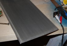
looks familiar to Gareth, I'm sure 🙂
Fin area is 6.5" wide now, but will be cut to fit exactly between the two vertical aluminum 'shields' that separate the centre from the modules. This will make a pretty large surface area and I can space the pass transistors out to distribute the heat. Worst case, I can add more devices.
I seem to recall that Hagerman paper described the technique for finding the inductance of a transformer. It involves finding the resonant frequency of the transformer secondary windings. Then some math...
That was actually capacitance.
There is a similar method for measuring inductance, and I used it to measure the secondary of my transformer. You use a function generator with sine wave output and wire a resistor in series with the secondary winding. Drive the winding and resistor with the FG, measure the voltage drop across the secondary and the resistor while you vary the frequency. Note the frequency where the voltage across each is equal. Use this frequency to calculate inductance using this formula: L=R/(2pi * f) L= inductance, R= the fixed resistor resistance (in ohms), f= frequency where the voltages were equal.
Yea, that's it. 😀
Did a board layout for the front end supply:
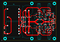
17cm x 12.5cm. I have built in a provision to connect the cap multiplier ground on either side of the disconnect:
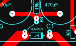
by connecting a jumper to one side (solid line) or the other (dotted line). This supply is the more important of the two, noise, hum and performance wise and that is why I'll start with this one. Once this is made, tested and all of the bugs worked out, I'll do the new soft start board.

17cm x 12.5cm. I have built in a provision to connect the cap multiplier ground on either side of the disconnect:

by connecting a jumper to one side (solid line) or the other (dotted line). This supply is the more important of the two, noise, hum and performance wise and that is why I'll start with this one. Once this is made, tested and all of the bugs worked out, I'll do the new soft start board.
Member
Joined 2009
Paid Member
Did a board layout for the front end supply:
View attachment 204989
17cm x 12.5cm. I have built in a provision to connect the cap multiplier ground on either side of the disconnect:
View attachment 204990
by connecting a jumper to one side (solid line) or the other (dotted line). This supply is the more important of the two, noise, hum and performance wise and that is why I'll start with this one. Once this is made, tested and all of the bugs worked out, I'll do the new soft start board.
I see you are "at it" 😀 You ribbed me for "tinkering" ,but here you do the same thing. Just the 2nd order cap multipliers running off the primary supply do it for me , scoped ... they show 10-20mv with heavy use.
I would ask , as you have said this amp was audibly sufficient , do you expect better sound with the changes ?
Still , I am glad this idea has caught on. A comment.... have you considered the timing factor. If the current stage PS "fires" up faster than the voltage stage PS , you might have issues. Not big ones , (I did it) .. a small "thump" or two. 😀 I solved this by having 2 diodes feed my voltage stages from the current stage supply , giving me a "stepped" voltage stage supply. First , the main +/- 75V (-.7v) powers up my voltage stages , then the secondary +/-85 volts from the voltage doublers kick in after a few more mS's. So , if you look at the voltage stage PS , it is at 74.2V instantaneously then rises to 85V a few microseconds later. The end result is not even a slight "tick". 😱 just something to consider. 🙂
OS
I would ask , as you have said this amp was audibly sufficient , do you expect better sound with the changes ?
Guten tag OS,
As I said in post #1:
Mainly, this is just whimsy - the existing power supply is more than adequate but I can't leave well enough alone.
There will be measurably better performance - much higher ripple rejection being the biggest benefit. I'm not at all convinced that that would translate to 'better sound'. You need to keep in mind that there isn't anything wrong with its sound now and that is through some very high resolution speakers. As well, there is a change over period - a day or two where I will be installing all of this shiny new gear. Audio memory, being as unreliable as it is, cannot be counted on to decide if there is a difference.
All of this, to me, is a hobby (one of them) - something to occupy my time. It is also a learning experience. I don't know it all yet, but I do gain a bit more knowledge when I do something different. An excellent example was my recent lab power supply build. I literally learned tons of valuable information during that project. I expect this one will be no different.
As for the supply powering up, the new soft start board will have a section that drives relays on (new) output boards. Currently, there is no start up/shut down muting, mainly because the amps don't have and on/off thump. This new power supply may change that. The output boards will be just 3 relays in series with each output (3 per side) that close ~2 seconds after the power is switched on and instantly open when it's turned off.
Currently, there is no start up/shut down muting, mainly because the amps don't have and on/off thump. This new power supply may change that.
And I contributed a solution to this (along with a wisecrack). Lighten up. I do value your contributions very HIGHLY , you realize .
OS
John,
You should not have issues with thumps if your front end voltage stabilises much quicker than the output voltage, because once the front end is stable it will try to keep the output at zero volt offset through dc feedback. I have completed my new ELD with higher front end regulated voltage and this was the case.
My personal suggestion is the place the front end supply with regulators in the spot of your current transformer and inrush suppression and move the bigger new transformer into a new aesthetically matching housing.
This would further benefit the amplifier system by magnetically and mechanically isolate the new mains transformer and you have no issues for what size transformer you would like to fit. You can even place more caps in the new box so your power supply will never be the limiting factor.
Kindest regards
Nico
John,
You should not have issues with thumps if your front end voltage stabilises much quicker than the output voltage,
...and move the bigger new transformer into a new aesthetically matching housing.
Thanks Nico,
The front end supply should come up before the main supply, since it will not be soft-started. I will try it with a module and see how it behaves.
I did have another reason for the relays on the outputs - DC detection that I may incorporate. In my haste to get the unit finished, I didn't do a lot of the things I wanted to do. Now is a better time; for one, I know a bit more and secondly, I can take the time needed to finish and test everything before I install it. That way I won't be doing without my precious for very long 🙂
I'd really prefer to not move the main transformer out of the case. I tried this approach before and the biggest problem was feeding the power back into the main chassis. It is an attractive solution though.
The transformer that I'm using now doesn't have a high enough voltage to give me regulation headroom. When I reuse it for another project, I may add to the winding to bump up the voltage but I don't want to do that on this one, as it could add some considerable time to the rebuild. With all of that said, I believe the new transformer will not be overly taxed by this and is probably a better match for this amp.
Last edited:
Fixed a couple of things on my layout:
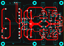
one of those was a connection from the 'centre tap' of the transformers to the main ground. I also added a terminal block for 24VAC out to power the softstart. Since each transformer is actually a 24-0-24, I can tap off the lower voltage to run the softstart.
I'll probably get this board made today and give it a try. Fingers crossed 🙂
Member
Joined 2009
Paid Member
If you're starting to consider protection circuits and you will implement a regulated supply, one of the options I liked was this one by Allen Newby:
http://www.diyaudio.com/forums/pass-labs/96737-fail-safe-power-supply.html
http://www.diyaudio.com/forums/pass-labs/96737-fail-safe-power-supply.html
MJL,
if you incorporate either a CCS supplied PSU or cap multiplier fed PSU, these have a very slow charge up. Could take a second to reach full voltage, depending on component choices.
if you incorporate either a CCS supplied PSU or cap multiplier fed PSU, these have a very slow charge up. Could take a second to reach full voltage, depending on component choices.
If you're starting to consider protection circuits and you will implement a regulated supply, one of the options I liked was this one by Allen Newby:
http://www.diyaudio.com/forums/pass-labs/96737-fail-safe-power-supply.html
Thanks Gareth (and for the heatsink 🙂 ),
That is more for current limiting and while that is a good idea, mostly what I want is DC detection. I'm looking at Rod Elliott's P33 and will most likely use this as a template. I have 6 channels to protect, so this in itself will be a big project.
MJL,
if you incorporate either a CCS supplied PSU or cap multiplier fed PSU, these have a very slow charge up. Could take a second to reach full voltage, depending on component choices.
I plucked the cap multi used here from my lab power supply, pretty much unchanged. It comes up nearly instantly on that.
I like the idea of having relays on the outputs to mute start/stop thumps (or other silly noises) and to make use of DC detection. I have space under the amp module 'shelves' to put the boards, so I may as well do it. If so, I may add yet another transformer, just to run the softstart and relays. I have a small 6.3-0-6.3 that would have enough gas to power these.
Member
Joined 2009
Paid Member
Be careful about putting EI (I assume the 6.3-0-6.3 might be an EI) transformers near the input circuitry, even if it is underneath. I've had hum induced in the front end of a tube amp from this - admitedly because it was choke loaded so there was another coil to couple to. If it doesn't have a belly strap, it might be worth adding one.
Be careful about putting EI (I assume the 6.3-0-6.3 might be an EI) transformers near the input circuitry, even if it is underneath.
I'll keep a weather eye of stray fields 😉
I found another candidate for the output stage transformer. When I say 'found', it means I found it where it wasn't lost - I'd just forgotten about its existence. While hunting for capacitors (another story) it turned up.
Gentlemen, the combatants:
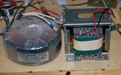
"in the red corner, the contender, wearing the clear trunks. Hailing from ATC-Frost and weighing in at a trim 9lbs even...'
😀 A little drama.
The toroid is 52-0-52 at 5.3A making it 550VA. Higher voltage than the EI, it will most likely be the one I'll use.
Caps - I don't have ANY! I thought I had more of the 4700uF, 80V caps that are presently populating the 'old' power supply. Alas, I don't. I do have a bunch of 50V 4700uF caps of the same sort and some 6800uF 63V. This is a problem...I may just pull 2 from the old supply to use in the front end supply and series the 50V ones in the main supplies. Certainly, spending $60 on new caps is out of the question.
- Status
- Not open for further replies.
- Home
- Amplifiers
- Solid State
- Patchwork 6: Power Supply Upgrade