I'm using The Valve Wizard's load line calculator to try to determine how to configure a particular 12ax7 stage for max output and no clipping.
http://www.freewebs.com/valvewizard2/LoadLinePlotter.xls
I will bypass the cathode's resistor with a "large" cap or use LED bias. I have red LEDs that provide 1.6 and 1.7 volts but I'm not afraid to use a resistor and cap since I think "hotter" bias may be better for me (and it's a guitar amp.)
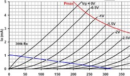
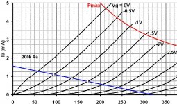
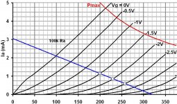
I have a 320V PS node available and I think the grid will see about 1Vp-p. I know that I should keep the bias point yielding at or under 1ma, and I guess I should probably keep the grid from reaching zero volts when driven. The total load I have on the output signal is probably around 200k.
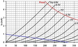
It looks to me that a 200k Ra with a bias at about -1V would provide a plate swing from 95V to 170V for an output of 75Vpp. And a 300k Ra would swing the plate from 75V to 155V for a swing of 80Vpp. Higher value Ra doesn't appear to yield more swing potential. And a 100K Ra looks to yield about 60V swing when biasing below 1ma at around -2V.
This is the 1st time I’m really trying to use load lines. It appears to me I should use a Ra of 300k? Are there other considerations that would affect the ideal plate resistor considering my goal of maximizing the output signal? Is 300k just crazy?
http://www.freewebs.com/valvewizard2/LoadLinePlotter.xls
I will bypass the cathode's resistor with a "large" cap or use LED bias. I have red LEDs that provide 1.6 and 1.7 volts but I'm not afraid to use a resistor and cap since I think "hotter" bias may be better for me (and it's a guitar amp.)
I have a 320V PS node available and I think the grid will see about 1Vp-p. I know that I should keep the bias point yielding at or under 1ma, and I guess I should probably keep the grid from reaching zero volts when driven. The total load I have on the output signal is probably around 200k.
It looks to me that a 200k Ra with a bias at about -1V would provide a plate swing from 95V to 170V for an output of 75Vpp. And a 300k Ra would swing the plate from 75V to 155V for a swing of 80Vpp. Higher value Ra doesn't appear to yield more swing potential. And a 100K Ra looks to yield about 60V swing when biasing below 1ma at around -2V.
This is the 1st time I’m really trying to use load lines. It appears to me I should use a Ra of 300k? Are there other considerations that would affect the ideal plate resistor considering my goal of maximizing the output signal? Is 300k just crazy?
Attachments
Your loadlines look good. 200-300K seem to be good values.
You could get a little more by using a CCS load for a flat loadline, and a gain of ~100.
When estimating the gain, you will however also need to consider the AC load represented by the next stage.
If you have a 500K gridleak on the next stage, you should draw a new AC loadline with the combined load (300K in parallel with 500K), centered on the operating point.
Svein.
You could get a little more by using a CCS load for a flat loadline, and a gain of ~100.
How the gain can become 100 when the mu of the tube is 100.
Does the CCS make the 12AX7's rp = zero ohms ?
How the gain can become 100 when the mu of the tube is 100.
Does the CCS make the 12AX7's rp = zero ohms ?
The gain becomes 100 precisely because the Mu is 100. The Rp of the tube is unaffected (barring changes due to nonlinearity).
The tube can be thought of as a variable voltage source in series with its Rp with gain of Mu (or a variable current source in parallel with Rp, with its Gm that of the tube in question)
The gain becomes 100 precisely because the Mu is 100. The Rp of the tube is unaffected (barring changes due to nonlinearity).
...and the gain is still 100 when there is 500 kohms load as a grid leak of the next stage ?
No.
For maximum swing, you want the next stage input Z to be as high as possible. Interposing a cathode follower might be worthwhile to squeeze out the most gain and bandwidth possible. The impedances are rather too high for effective use of a plate choke.
For maximum swing, you want the next stage input Z to be as high as possible. Interposing a cathode follower might be worthwhile to squeeze out the most gain and bandwidth possible. The impedances are rather too high for effective use of a plate choke.
Is it really necessary to try to wring as much voltage swing as possible out of a 12ax7 gain stage? What are you planning on driving with it?
Thanx for the feedback.
It is a boosting stage after an “effects loop.” It’s then mixed back in with the “dry” signal path and I could use a little more than from its current configuration of a 100k and 252V on the current PS node. There are other approaches I could have used for the “mixing” but I’ve already gone way down the current configuration and just need a little more if possible.
It's output goes to a "mix" control which then goes on to a LTPI. Overall impedance from those is about 200k (without considering it's own plate resistor.) Exactly how do I "draw a new AC load line with the combined load (300K in parallel with 200K), centered on the operating point." ?
I think 300k||200k is about 125k but how do I "draw" that and use it? Do I use only this new line's slope and "slide" it onto the DC idle point? Or do I draw the 125k line in a normal fashion and do something else?
Will this change the ideal Ra value for me or does it just accuratize the projected output strength?
I think 300k||200k is about 125k but how do I "draw" that and use it? Do I use only this new line's slope and "slide" it onto the DC idle point? Or do I draw the 125k line in a normal fashion and do something else?
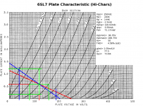
You do it like this (attached). The normal DC Loadline comes in at:
Vpk= 120.62Vdc
Ipq= 0.59mA
The AC Loadline is based on the expected impedance, in this case: 144K. So figure the deltaI:
deltaI= 120.62 / 144E3= 0.84mA
Add that to the DC bias current: deltaI + Ipq
0.59 + 0.84= 1.43mA
Find that point along the vertical (plate current) axis, and draw the AC Loadline between that point and the Q-Point on the DC Loadline. Done.
Will this change the ideal Ra value for me or does it just accuratize the projected output strength?
It does change the Ra value completely so far as AC operation is concerned. Sometimes, it makes a difference, and sometimes it doesn't. (Inthis case, it made a big difference.) If the AC load is within +/- 5% of the DC plate load, I just ignore the difference. That's probably well within component tolerance, and hollow state is a good deal more "forgiving" than solid state design anyway.
Attachments
The gain becomes 100 precisely because the Mu is 100. The Rp of the tube is unaffected (barring changes due to nonlinearity).
Bigwill, I did not get your answer yet.
How the gain of a 12AX7 can become 100 with CCS when there is 500 kohms grid leak of the following stage as a load ?
Bigwill, I did not get your answer yet.
How the gain of a 12AX7 can become 100 with CCS when there is 500 kohms grid leak of the following stage as a load ?
It doesn't. It is 100 when combined (AC) load is infinite. Of course you know how it goes with ideal current sources which present infinite impedance ... they require infinite voltage to operate 😉
But it can get pretty close to mu when grid leak of the following stage is large enough.
Yes at the time I was imagining an unloaded gain stage. Of course capacitively coupled to the grid-leak the AC load becomes 500k, and thus the gain is reduced slightly.
Finally got to it. Closest value I had is 330k for the plate. A 2.2k cathode yields 1.28v for 0.6ma. PS node is 319 and the plate is 122. Definitely an improvement in output from that triode. Not huge but it's what I needed for the application.
I checked the max swing on the grid and it's around 0.5p-p. I could probably go a little hotter on the bias for a little more gain w/o reaching saturation but I'm happy for now.
DC load line:
I checked the max swing on the grid and it's around 0.5p-p. I could probably go a little hotter on the bias for a little more gain w/o reaching saturation but I'm happy for now.
DC load line:
Attachments
- Status
- Not open for further replies.
- Home
- Amplifiers
- Tubes / Valves
- 12ax7: How to maximize output?