Hi Guys
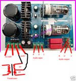
I purchased a few of these pre-made 'pre-amp' boards to play with , as I'm trying to understand tube circuits. I've been using them as a gain stage for resistor i/v with TDA1541 dacs , as well as some PCM chips. The board comes with Chinese 6N1(1) tubes. I've also used 6N2 & 6N2P-EV tubes for higher gain. I'm able to use 25-33ohm i/v resistors with these.
I like the sound , I just don't know if i should😀 . Does this circuit appear to be well designed for my (or any other) application? Also , any idea of the output impedence?
Thanks
Attachments
Last edited:
so do I - hate to chase datasheets for tubes used in project , just to answer on someone's question

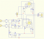
1: Your schematic must be incorrect, there is no way this circuit woudl ever sound like anything with 220R/2 anode load.
2: Whoever designed the circuit saved few cents on a couple of diodes and four capacitors, end result being that heater voltage is at the lowest end of specified range and that heater voltage regulators will have easier time oscillating, should they so desire.
3: With both halves of each tube paralleled I'd say this a waste of a perfectly good tube (which could instead have been used as cathode follower, presenting far lower impedance at the output).
4: I don't see grid stoppers anywhere.
My conclusion is this was put together by some kid for his elementary school project. Strip the board for bits, draw your own PCB and rebuild it properly.
1: Your schematic must be incorrect, there is no way this circuit woudl ever sound like anything with 220R/2 anode load.
3: With both halves of each tube paralleled I'd say this a waste of a perfectly good tube (which could instead have been used as cathode follower, presenting far lower impedance at the output).
The tube symbols are a bit unfamiliar, but after a close examination the topology appears to be SRPP.
Might not be completely hopeless, especially if it sounds good 🙂
... but this is a DIY forum; Of course it can be improved!
Svein.
The tube symbols are a bit unfamiliar, but after a close examination the topology appears to be SRPP.
Might not be completely hopeless, especially if it sounds good 🙂
... but this is a DIY forum; Of course it can be improved!
Svein.
Yes , this is an 'SRPP PRE AMP KIT' , per the listing . Fully assembled. These are available from several Asian vendors , on ebay , for less than $35 shipped to the US. I purchased 4 of these for $100 delivered . The transformer is the more difficult part , as it can get expensive. I was looking for something to provide the gain needed. As long as I use MY pre amp after this board, I can even use a 10 ohm resistor for i/v , but I'm near maxed out on volume.
Thought these might be of use to someone else , if the design makes sense??
The tube symbols are a bit unfamiliar, but after a close examination the topology appears to be SRPP.
Oh boy, I could never make this out by myself, I got lost during guesswork

Looks like they saved up a couple more components in this case, SRPP is a very fine stage ... for driving segments of telco cables of known, fixed impedance. Why do the Chinese fancy these for audio line duty ? They are bound to run into various different loads 😕
This is what the LAMPIZATOR site seems to love. Also the 6N2P-EV is his fav.
Since I have a large inventory of 80's cd players , mostly 1541 dacs , I was looking for something that would fit inside the players. It takes dome figuring , but it fit fairly well in Magnavox and lower end Sonys with the 1541 dac. Gain is about 100db , per the 6N2P data sheet. Not sure how SRPP affects the gain.
How does one determine output impedence?
Oh boy, I could never make this out by myself, I got lost during guesswork
Looks like they saved up a couple more components in this case, SRPP is a very fine stage ... for driving segments of telco cables of known, fixed impedance. Why do the Chinese fancy these for audio line duty ? They are bound to run into various different loads 😕
It's trendy.. Think I've said that before.. 😀 What you say is true, but even so it performs at least adequately into a wide range of load impedances.
This board is crying for a conversion to mu-follower which provides a lot more gain for this I/V conversion application. Would require the addition of two resistors and a cap per channel - might be manageable with just a couple of etch cuts, and the components required could be installed on the bottom side of the pcb.
WRT the schematic, you can download LTSpiceIV (it's free!) from Linear Tech and use that to draw tube schematics. If you install some tube libraries as detailed in other threads you can even simulate the circuit.
Here is the link: http://www.linear.com/designtools/software/ltspice.jsp
Here is the link: http://www.linear.com/designtools/software/ltspice.jsp
I bought one of these about a year ago to experiment with. Using my laptop for the source, this required about 20dB of attenuation on the input. I put a 3 channel source selector and passive tone control on the front end. The tone circuit provided enough attenuation. I used a 100K dual-gang pot at the output. It actually performs well.
Last edited:
It's trendy.. Think I've said that before.. 😀 What you say is true, but even so it performs at least adequately into a wide range of load impedances.
This board is crying for a conversion to mu-follower which provides a lot more gain for this I/V conversion application. Would require the addition of two resistors and a cap per channel - might be manageable with just a couple of etch cuts, and the components required could be installed on the bottom side of the pcb.
I originally used a 75 ohm i/v resistor (tda1541). It sounded fine , but way to much output. I started lowering the resistor value. 33 ohms seems pretty good with the gain provided by this circuit. Still more than I need.
I'm quite certain this board could be refined , but very effective (for me) and easy to work with as it stands.
If you install some tube libraries as detailed in other threads you can even simulate the circuit.
Can you give some link(s) to find those tube libraries ?
How does one determine output impedence?
Output impedance of SRPP is (I believe) roughly half the output impedance of a straightforward common cathode stage. This is however pointless if SRPP isn't loaded with the same load it was designed for. These can vary wildly (say from 4.7K at the bottom end and all the way up into 100K or megaohm range).
Can you give some link(s) to find those tube libraries ?
Here's one thread I participated in, I posted some there, and there are some links to other libraries as well as lots of useful information.
Here: http://www.diyaudio.com/forums/tubes-valves/94067-tube-spice-models.html
In the old days you could try LTspice and my userid in advanced search and get some of the other stuff I posted.
- Status
- Not open for further replies.
- Home
- Amplifiers
- Tubes / Valves
- Could anyone opine on this circuit?