Has anyone compared this with the previous board with lower capacitance? I have the prevous board and was wondering if I should increase the capacitance. Thanks!
I have my board almost finished. I just need to desolder one part which is the wrong value and then I can begin testing my work. As I'm new to diy I would certainly appreciate it if someone could answer the following questions.
1) Are the TO-247 heat sinks in the v1.0.4 bom adequate for 200mA current? If not can someone provide a link to a heat sink I can order.
2) I am currently using Uriah's Lighter Note LDR kit and would like to use it as the volume control for the dcb1. Should I be going source->dcb1->lighter note->amp? Or should the lighter note be before the dcb1?
3) Also, I have two sources--digital and vinyl. What would be the best solution with my configuration if I need two inputs?
I apologize in advance if these questions have been answered before. I searched through this thread repeatedly without finding answers to my questions.
1. No. Use 1C/W per rail with isolation pads, or bolt Mosfets to chassis with pads.
2. Before.
3. Mezmerize with on board relay switched inputs, or a mechanical input switch and Hypnotize.
2. Before.
3. Mezmerize with on board relay switched inputs, or a mechanical input switch and Hypnotize.
Knassari- On 3, I uses a DPDT type switch. It's cooler looking than a knob IMO. 🙂
Additionally, I think Oliver used a third party relay PCB to integrate with the Hot Rod hypnotize.
I can also send you some medium size CPU heatsinks for cost of shipping if you know how to use a tap,
you can use thermal epoxy and glue them to copper or aluminum. That's what I did.
Additionally, I think Oliver used a third party relay PCB to integrate with the Hot Rod hypnotize.
I can also send you some medium size CPU heatsinks for cost of shipping if you know how to use a tap,
you can use thermal epoxy and glue them to copper or aluminum. That's what I did.
Hi,
does anyone have isolation pads for the TO-247 package. I picked up some silicone pads, but unfortunately a bit too small (T0-200) I think.
(They didn't have any that fit the mosfets I needed).
I'll send some $ via paypal, just PM me.
Thanks,
JG
does anyone have isolation pads for the TO-247 package. I picked up some silicone pads, but unfortunately a bit too small (T0-200) I think.
(They didn't have any that fit the mosfets I needed).
I'll send some $ via paypal, just PM me.
Thanks,
JG
3) Also, I have two sources--digital and vinyl. What would be the best solution with my configuration if I need two inputs?
I plan on using one of these for a few more inputs...
stereo audio channel input selector board kit ! - eBay (item 220497959345 end time Jan-13-11 05:32:17 PST)
Salas, Teabag, MrSlim -- Great information, Thank you! You've saved this neophyte loads of time.
Teabag -- I'll take the heat sinks. I'll send you a pm in a bit.
Teabag -- I'll take the heat sinks. I'll send you a pm in a bit.
I can also send you some medium size CPU heatsinks for cost of shipping if you know how to use a tap,
you can use thermal epoxy and glue them to copper or aluminum. That's what I did.
Do you have a picture of how you did it? I might be interested in getting some of those heat sinks from you also..
Hi, has anyone had any experience with these chassis?
Autocostruire - made in italy audio tools
They look great, they might fit the bill.
Autocostruire - made in italy audio tools
They look great, they might fit the bill.
Merlin - they are Modushop chassis parts, exactly the same. Very much recommended. See post #693
modushop.biz
modushop.biz
Last edited:
2) I am currently using Uriah's Lighter Note LDR kit and would like to use it as the volume control for the dcb1. Should I be going source->dcb1->lighter note->amp? Or should the lighter note be before the dcb1?
source->dcb1->lighter note->amp is exactly how I did it and it works fine.
Merlin - they are Modushop chassis parts, exactly the same. Very much recommended. See post #693
modushop.biz
Great, thanks.
Did you drill out the chassis yourself?
Great, thanks.
Did you drill out the chassis yourself?
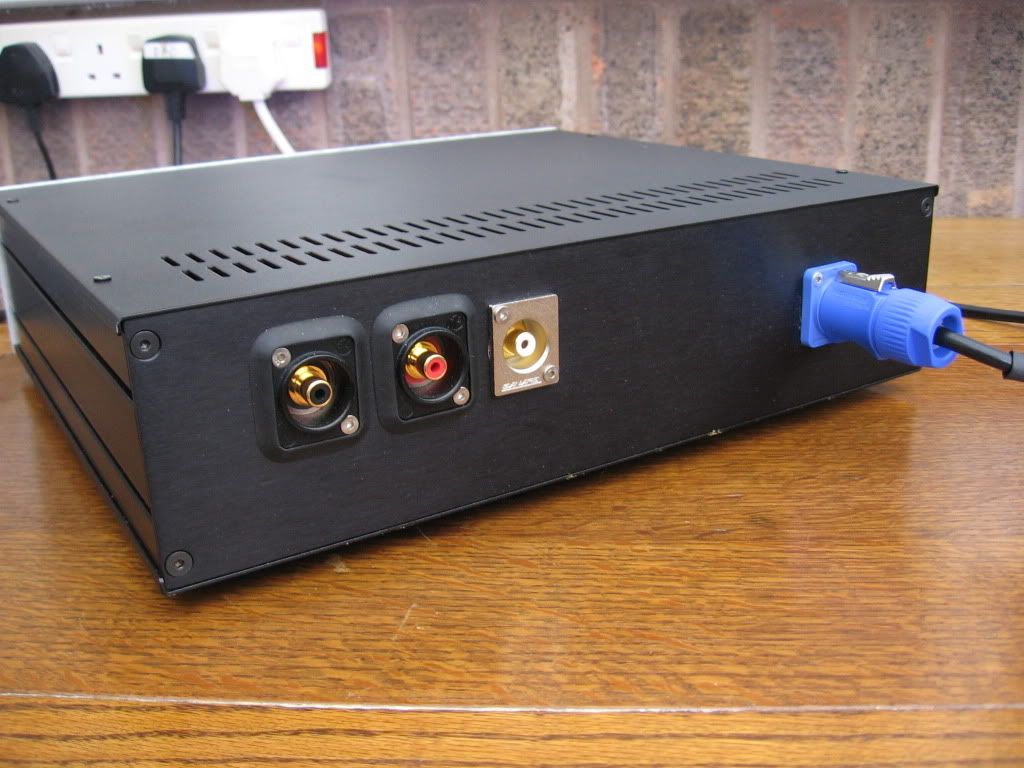
I did yes, just using a bosh hand drill. Very easy to drill as I bought the case with 3mm front panel for now. I intend to have some nice custom 10mm panels made by Schaeffer AG one day.
The large holes for switch, power inlet and RCA sockets were cut using metal hole cutters like this:
BOSCH|2608580402|HOLESAW, HSS, BI-METAL, 22MM | Farnell United Kingdom
http://uk.farnell.com/ruko/106-201/arbor-holder-with-pilot-drill-type/dp/379128
An externally hosted image should be here but it was not working when we last tested it.
Last edited:
The volume pot (any type) should be between source and DCB1 so to keep a low and steady impedance output to the amp.
George, who designed the Lightspeed, recommends that the Lightspeed be last in the chain feeding the Power Amplifier.
He says it gives better sound this way.
However, due to the high output impedance of the LDR combination, the passive volume control must be connected with very short cables, or none at all and the RF attenuation cap inside the Power Amplifier must be scaled to suit the source output impedance.
using source > DCB1 > long cables > LDR/Power Amp allows the lowish output impedance of the DCB1 to drive the cables and the LDR/Power Amplifier to be designed as a compatible pair.
The alternative, is to use long cables to the power amplifier and use the DCB1 to drive these cables.
This would result in the LDR/DCB1 being designed as the compatible pair.
source > LDR/DCB1 > long cables > Power Amplifier.
Choose which suits your location of equipment and skills to design the appropriate combo.
A further (expensive) alternative is:
source/DCB1 > long cables > LDR/DCB1 > long cables > Power Amplifier.
This uses the lowish output impedance of the DCB1 to drive all the cables in the system.
And finally:
source>LDR>Power Amplifier where each side of the transmit/receive pair is designed to be compatible.
Last edited:
Yeah, I could have sworn I read in the lightspeed thread that the optical control is placed just before the power amp. I admit I tried it, worked first time, sounded good so I left it. I'm intrigued by Salas' suggestion and will give it a go just out of interest.
I'm running the Legato SE which technically means that I have a buffer feeding into another buffer, Whether this is a good thing I don't know. I'll ask the guys on the lightspeed thread and see what they suggest.
Andrew - when you say the RF attenuation cap, do you mean the input cap? I have a dual mono amp using Avondale NCC200 boards which are based on the Naim RCA circuit.
Cheers
Thank you for the explanation Andrew. I'll try the LDR in front and behind the dcb1 and see what I prefer. May I ask what length is suitable for a 'long cable'?
I think you mean DC blocking cap when you say "input" cap.when you say the RF attenuation cap, do you mean the input cap?
The DC blocking cap is the High Pass filter.
The RF cap to ground is the Low Pass filter.
2, 3, 4, 5m.what length is suitable for a 'long cable'?
By the time you get to 10m, I suspect you may be looking for a more capable line driver.
I did yes, just using a bosh hand drill. Very easy to drill as I bought the case with 3mm front panel for now. I intend to have some nice custom 10mm panels made by Schaeffer AG one day.
The large holes for switch, power inlet and RCA sockets were cut using metal hole cutters like this:
BOSCH|2608580402|HOLESAW, HSS, BI-METAL, 22MM | Farnell United Kingdom
RUKO|106 201|ARBOR HOLDER WITH PILOT DRILL | Farnell United Kingdom
Is that a 2u or 3u case?
I'm looking at a 2u, and the larger caps just fit in the case (it would leave about 10mm room up top).
Oh, one other thing, I thought the 3mm front panels had holes in them for rack mounting?
I'm looking at 2x of 1PS02PN these for my blue dcb1 buffer.
Thanks,
JG
Last edited:
- Home
- Source & Line
- Analog Line Level
- Salas hotrodded blue DCB1 build