You are correct sir!!! Fat fingers and all.
I was just out in the garage looking at all the bits for the chassis and actually, there is enough room for a simple pre amp in the chassis if I can't just increase the gain on the boards (which I don't know if I can do to begin with)(email sent to Gary Kaufman on that)
I was just out in the garage looking at all the bits for the chassis and actually, there is enough room for a simple pre amp in the chassis if I can't just increase the gain on the boards (which I don't know if I can do to begin with)(email sent to Gary Kaufman on that)
I hear ya, with me it ain't just the fingers that are fat. 😀
BTW, if it is Steve's original design there is no gain and no way to increase it without another tube as it is all CF based. If you are using a PCB (can't stand those things myself) then you would have to add a separate point to point wired gain stage or another board.
BTW, if it is Steve's original design there is no gain and no way to increase it without another tube as it is all CF based. If you are using a PCB (can't stand those things myself) then you would have to add a separate point to point wired gain stage or another board.
Last edited:
That's what I was thinking but just wanted to confirm it. I'll have to do some thinking on this one.
That's hilarious, suggesting one with an input transformer instead. 😀
Sounds to me your system will end up pretty complicated, but by all means, it may also end up good sounding. (Sorry, I'm an KISS kinda guy).
If you're gonna have active crossovers, tube or SS, you are gonna have caps in the signal path anyhow, so no point in looking for a DC coupled preamp.
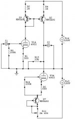
For the sake of discussion, here's an attempt I did while at college, trying desperately to combine tubes with DC coupling. (In those days I was heavy into the discussion of which cap was good and bad, and the big waste of time got me to conclude no cap is better than even Audio Note silver foils...
Today I am more interested in circuit ideas than such **, and listen to the muci more than the sound.
Anyhow, these circuits combined tubes and SS and the matching load on the negative rail balanced out offset, even temp drift to some extent. The transistors were superglued together and wrapped in copper foil for identical temp.
The load resistors set the gain, the 10kohms, and can be variable for volume control.
They actually worked satisfactory, but I only had one breadboard those days, and after a while the circuits became other creations. Perhaps some day I'll tweak them a little and build them again.
If you're gonna have active crossovers, tube or SS, you are gonna have caps in the signal path anyhow, so no point in looking for a DC coupled preamp.
For the sake of discussion, here's an attempt I did while at college, trying desperately to combine tubes with DC coupling. (In those days I was heavy into the discussion of which cap was good and bad, and the big waste of time got me to conclude no cap is better than even Audio Note silver foils...
Today I am more interested in circuit ideas than such **, and listen to the muci more than the sound.
Anyhow, these circuits combined tubes and SS and the matching load on the negative rail balanced out offset, even temp drift to some extent. The transistors were superglued together and wrapped in copper foil for identical temp.
The load resistors set the gain, the 10kohms, and can be variable for volume control.
They actually worked satisfactory, but I only had one breadboard those days, and after a while the circuits became other creations. Perhaps some day I'll tweak them a little and build them again.
Attachments
It does take a while and a lot of tweaking to get it all right, but that is the fun of it. I was a full range and SET amp guy for a long time, but that system went to my daughter.
What is the gain of those scheems? I am looking for just a bit of gain and have been thinking about the 26 tube for the pre. Of course I'd have to use Rod Coleman's DHT boards to keep it real clean.
What is the gain of those scheems? I am looking for just a bit of gain and have been thinking about the 26 tube for the pre. Of course I'd have to use Rod Coleman's DHT boards to keep it real clean.
The volume pot and selector switch are going into a Lionel transformer (see pic).
Man, I looooove that Lionel transformer!! Now I want one.
The passive parts under the butter covers is way cool, too. Bravo!
Yep, it is a cool thing. I am going with the transformer volume pots with remote. I was at my Mom and Dad's the other day and found 20 lbs of lead plate the same size as the bottom of the inside of the transformer. So that thing is going to be HEAVY!!!
It does take a while and a lot of tweaking to get it all right, but that is the fun of it. I was a full range and SET amp guy for a long time, but that system went to my daughter.
What is the gain of those scheems? I am looking for just a bit of gain and have been thinking about the 26 tube for the pre. Of course I'd have to use Rod Coleman's DHT boards to keep it real clean.
Man I like your functional artwork🙂
The gain is a little tricky to calculate for one who hasn't done so in awhile🙂 If the cathode resistor is bypassed, and very small resistance is used in the mirror, you get pretty much a current swing on the output close to the Gm of the tube. So if Gm is 10mA/V, and you use a 10kohm resistor for load, the gain is 100x, or 40dB. Here I use unbypassed cathode resistor, relatively large emitter resistors in the mirror, and a tube in parallel with tthe loading resistor, so it gets complicated. Per simulations, a 1500ohm resistor at the output gives a gain of about 6dB. With such low resistance, the offset is very low as well, but not zero. Probably low enough (some ten mV) that it can be used directly coupled. Unless the amp is very sensitive.
This circuit's best thing going for it is the fact that you can load it however you like without messing with the linearity too much. That is why using a stepped attenuator can give you a shunt type volume control that sounds pretty damn good.
I think I understand Semper. Do you have a scheem I can look at?
Hey DJN
This Blue Marble Tube Preamp sculpture is Cool, Real piece of Art.
Best Regards🙂
Thanks Banat. The chassis for this tube crossover/pre amp has over 200 brass and copper parts. Should be wild.
Its possible to use a Circlotron to get a direct-coupled balanced output. You have to use a servo to make it happen.
Nice work with the blue marble!
Nice work with the blue marble!
Thanks Atmasphere. My TT is made out of maroon/dark green/white/black marble. It looks very cool and is not even finished yet.
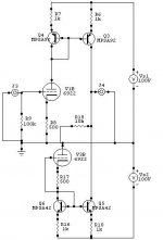
Something like this?
Something like this?
Attachments
Last edited:
Yes, something like that. This circuit will have feedback as part of its operation. If you want zero feedback, it will have to be something a little different.
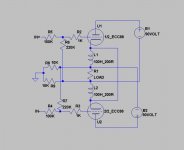
I've been thinking. What if we take that schematic you just put up, delete the 100K input resistors, and replace each of the 220K resistors with a pair of 110K resistors in series?Do you have a scheem I can look at?
Then at the point where each pair of 110K resistors meet, we put a 10uf cap to ground on each side.
Now there is no audio feedback, which is why we could get rid of the input 100K resistors. Instead, there is only DC feedback, to the tune of nothing over about 0.15 Hz, on a 6DB slope.
Now you have the zero feedback audio circuit, but with DC correction. You would need a set of input coupling caps (0.47uf ought to do well) so that the grid voltages are not messed with by the source.
- Status
- Not open for further replies.
- Home
- Amplifiers
- Tubes / Valves
- IS there any OTL pre amps out there?