Can an EL84, possibly an EL84M
Sovtek EL84M
be used in a Simple SE using a straight pin adapter?
THD YJUni EL84 to 6V6 Adapter.
My B+ is around 425V-430V using a 5AR4 rectifier. I was thinking of using a 5R4 to drop the voltage by 20-30V or so. I believe this would take me around 400V or so. The drop across the cathode resistor would probably another 20V or so, which leaves me with about 375V across the tube. I believe this gets me in the ballpark. I know about the lack of slow startup using the 5R4.
Does anyone see any issues with this??
I think you could build an adapter yourself. Not sure I would be forking over $90 for a socket saver and a 9pin socket. I have no comment on whether it will work or not but I think you could make the socket adapter yourself.
I think you will be on the edge of meltdown. I have not tried the Sovtek EL84M, but the regular Sovtek EL84 will glow if fed 350 volts or so. I have tried quite a few different EL84 types in the Simple P-P and the best versions for high voltage use are the JJ's.
The EL84 will draw about half the current that a 6L6GC or EL34 will draw so your B+ will go up and the drop across the rectifier will be less. Also the cathode voltage is usually 12 or 13 volts.
The JJ's will eat 430 or more volts of B+ but get excited if the screen voltage goes above 340 or so. Some of the other EL84's won't even go that far.
I am not sure if the Yellow Jackets with current limiting built in would help or not, but for the price they charge, I'll never find out. I would be more tempted to buy a $45 power transformer that results in a 320 volt B+ voltage (Allied 6K56VG) and make my own adapter for a few bucks using the tube bases and sockets from AES.
I have a Simple SE using the Allied 6K56VG and I run 6V6's in it. It sounds nice. Two circuit changes are needed. The cathode resistors for the output tubes need to be reduced. (I think they are 270 ohms) and you need to jumper across the 10 K resistors feeding the CCS chips.
I think you could build an adapter yourself. Not sure I would be forking over $90 for a socket saver and a 9pin socket. I have no comment on whether it will work or not but I think you could make the socket adapter yourself.
Yeah, they are too expensive. My question was more about the voltages rather than the actual pin adapter itself.
6P1P to 6V6 adaptors. Could probably do with built-in grid stoppers but works as is.
Probably no good for long term use...
Probably no good for long term use...
Last edited:
The EL84 will draw about half the current that a 6L6GC or EL34 will draw so your B+ will go up and the drop across the rectifier will be less.
I would be more tempted to buy a $45 power transformer that results in a 320 volt B+ voltage (Allied 6K56VG).
Another option would be to add another filter choke in the power supply, just before C1. It required cutting a trace on the circuit board, but is otherwise a very simple modification. This dropped the B+ on my Simple SE from 455V down to 335V, which should be perfectly safe for EL84.
If I can scare up a couple 9 pin adapters, maybe I'll try out the EL84.
I think you will be on the edge of meltdown. I have not tried the Sovtek EL84M, but the regular Sovtek EL84 will glow if fed 350 volts or so. I have tried quite a few different EL84 types in the Simple P-P and the best versions for high voltage use are the JJ's.
Good information. Thanks.
I am going to avoid any kind of modifications, radical surgery, or meltdown situations at the moment, and leave the amp as is. The amp sounds freaking great. But if I can take the thread on a slight tangent, here is what prompted my question:
So, I have 2 simple se's hooked up in PP. Some of you have seen the thread I started about it a while ago. I ended up going with JJ 6V6S tubes, and that is the ticket for sure.
I put the output of the amp on a scope, and ran a 200Hz (why 200, I don't know) sine wave through it. I can get about a 5.5V peak on the wave, before the wave gets distorted, and the harmonics really kick in. So thats almost 4W peak in triode mode with an 8 ohm speaker. I flicked the switch to UL, and assumed I would be able to clear 7 or 8V without distortion, but it does not work that way. 5.5V seems to be the threshold of distortion even in UL. It got me to wondering if the similarly power sized EL84 would do better in UL, netting me around the 8-10W or so I was expecting in PP. BTW, when I switching between UL and triode using the EL34's the power difference was quite clear.
Anyway, the way my amp is set up now is pretty much perfect for my speakers, so if more than a simple pin converter is necessary, this idea will stay as a thought experiment for now. Of course there are other ways to get more power, if I need it down the road, like EL34's in triode or UL, so I'm not going to sweat it. But my question about the 6V6S's topping out at 4W peak in UL is still curious to me. I would think I could get more.
Last edited:
It might be interesting to put your scope on the grid of the finals, and confirm the first stage isn't what's starting to distort. Though I'd be very surprised if it was, unless it's starved for voltage. With the B+ conditions you report, that should not be the case.
some pics w scope
This doesn't seem to be the problem, but is a reasonable suggestion for sure. But I did take some other measurements which are very interesting. This may turn into a lesson more about speakers rather than amps, or maybe a combination of both, but here's what I did.
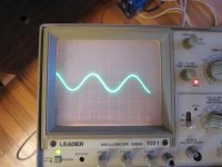
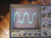
There are 3 pics attached here- all are taken from the speaker terminals, and with amp in triode mode. The first is a beautiful 5V 200hz sine wave running into a 9 ohm (had only 9ohm on hand) dummy 25W resistor. The next pic is an almost as sexy 10V sine wave going into a resistor. The top of the wave begins to compress above 7V, but it still looks pretty nice.
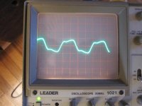
The problem child is the third pic. It is the same 200Hz sine wave, about 5V going into the actual speakers. Harmonic content is pretty obvious, and the wave looks more like an iceburg or a mountain range than the original sine wave. The speakers used are Klipsch RF3-II. They have a sensitivity of around 98db, and are rated at around 150W. Is this some kind of damping factor issue?
Fortunately for my particular situation, normal listening is at about 2-3V peaks. Very loud listening nearly ear bleeding can be had at around 5V, so I am operating in the sweet spot of this amp. If I ever switched speakers I may have an issue, but its not a problem for me now. But I am very curious what others have to say.
It might be interesting to put your scope on the grid of the finals, and confirm the first stage isn't what's starting to distort. Though I'd be very surprised if it was, unless it's starved for voltage. With the B+ conditions you report, that should not be the case.
This doesn't seem to be the problem, but is a reasonable suggestion for sure. But I did take some other measurements which are very interesting. This may turn into a lesson more about speakers rather than amps, or maybe a combination of both, but here's what I did.
There are 3 pics attached here- all are taken from the speaker terminals, and with amp in triode mode. The first is a beautiful 5V 200hz sine wave running into a 9 ohm (had only 9ohm on hand) dummy 25W resistor. The next pic is an almost as sexy 10V sine wave going into a resistor. The top of the wave begins to compress above 7V, but it still looks pretty nice.
The problem child is the third pic. It is the same 200Hz sine wave, about 5V going into the actual speakers. Harmonic content is pretty obvious, and the wave looks more like an iceburg or a mountain range than the original sine wave. The speakers used are Klipsch RF3-II. They have a sensitivity of around 98db, and are rated at around 150W. Is this some kind of damping factor issue?
Fortunately for my particular situation, normal listening is at about 2-3V peaks. Very loud listening nearly ear bleeding can be had at around 5V, so I am operating in the sweet spot of this amp. If I ever switched speakers I may have an issue, but its not a problem for me now. But I am very curious what others have to say.
Attachments
I am going to guess that your speakers are less than 8 ohms at 200 Hz. Every speaker system has an impedance VS frequency curve. Sometimes the manufacturer publishes it, sometimes they don't. Google couldn't find the graph for your speakers and it isn't on the Klipsch site either. My Yamahas are "8 ohms nominal" but vary from 6 ohms to 40 ohms across the audio range. You might try your test with a tone closer to 1KHz since that is where most manufacturers rate their speakers.
I am going to guess that your speakers are less than 8 ohms at 200 Hz. Every speaker system has an impedance VS frequency curve. Sometimes the manufacturer publishes it, sometimes they don't. Google couldn't find the graph for your speakers and it isn't on the Klipsch site either. My Yamahas are "8 ohms nominal" but vary from 6 ohms to 40 ohms across the audio range. You might try your test with a tone closer to 1KHz since that is where most manufacturers rate their speakers.
Your probably right, in that I could probably get lesser distortion at a higher power using a 1KHz tone. I chose a lowish frequency since when listening to music, its often the lower notes that give the peaks- that and I suppose transients from percussion. So I think the 200Hz is a kind of a real world situation- plus the 200Hz tone tends to not cut through by eardrums like a 1K. But I will put some ear muffs on and report back.
This is an important discovery for me. You may buy an amp rated at X watts, but in reality, the full power may not be entirely usuable across the spectrum, especially in the lower frequency where it is needed most. Interesting! I am guessing that this situation is more extreme in a tube amp without feedback, with the other extreme being solid state with feedback. Is this a damping factor issue?
Can you tell us something about your output transformers? Maybe try it with cathode feedback?
I'm using 2 SSE boards together in PP, so I don't think I can use cathode feedback. I am using 10W Edcor PP transformers, but I also used their 25W versions with pretty much the same effect.
I tried running higher frequencies through the amp, including 1K, and yes, I can get a pretty large voltage swing this way- pretty close to 10W with no visual or audible distortion on the wave (at least I don't see any on the scope, and can't detect it with my ears).
I also just popped in some EL34's, and at 200Hz, 5V (10vpp) is pretty much the point that the gross distortion starts. I also tried 40Hz, at which I get less distortion at that voltage.
My final conclusion to all of this, with the help of all of you, is that the impedance curve of the speaker is definitely playing a big part. And I think back emf is at work. At low frequencies, the woofer is moving like mad. If I tap on the woofer with my fingers while looking at the scope a lot of voltage is generated at the outputs. I think the large movement of the woofer, at possibly a slight delay, pushes back on the amp, generating distortion. This seems to be supported by the fact that similar distortion happens at similar voltages with both a 6V6 and EL34 tube, so I do not believe its an issue of overdriving the tube. On top of that, I do no get any distortion on the scope until about 10-12V regardless of frequency while running the amp with a resistive dummy load.
I am thinking the this distortion is related to the physical distance that the woofer is moving, and any delays associated with that physical movement, so the kind of distortion I am getting is proportional to distance and speed of the woofer. So if my speakers were lower sensitivity (say 90db vs 98), I would see a similar distortion, but only at the higher power necessary to drive the woofer the same distance in travel. Anyway, these are all hunches, and not really backed up by much. Feel free to dubunk as necessary.
Having said all this, its not really an issue for me- more of a learning exercise. Musical material, even with peaks much higher than 5V, and not resonating at a single frequency, sound just fine, and I am rarely listening above 2-3W peak anyway.
Last edited:
Can an EL84, possibly an EL84M be used in a Simple SE using a straight pin adapter?
OK, here it is...

http://i69.photobucket.com/albums/i43/Ty_Bower/Simple SE/P1150444.jpg
I cut the trace on the board and added an extra choke to the power supply, as described in #6. I haven't checked B+, but I'd expect it is around 335. The plates of the tubes are a nice dull grey color.
OK, here it is...
http://i69.photobucket.com/albums/i43/Ty_Bower/Simple SE/P1150444.jpg
I cut the trace on the board and added an extra choke to the power supply, as described in #6. I haven't checked B+, but I'd expect it is around 335. The plates of the tubes are a nice dull grey color.
Cool! How do you like the sound?
I think I will hold off on trying this at the moment, but I may give it try down the line. What size choke was necessary to drop the B+ by so much? I have a 1.5H, 60 Ohm choke laying around. Will this do it? Typically, my B+ using the newer (higher voltage) 6V6's is around 430V.
You just cut the trace between R2 and C1, and inserted the choke there, right?
You just cut the trace between R2 and C1, and inserted the choke there, right?
Last edited:
What size choke was necessary to drop the B+ by so much? I have a 1.5H, 60 Ohm choke laying around. Will this do it?
You just cut the trace between R2 and C1, and inserted the choke there, right?
Yes, that is the place to make the cut. I made a sketch a long time ago. Ignore where I said "jumper", but the cut is the same. You are also correct in noting where to put the choke. It is easy to do - just use the terminals at L1-O2 and SW1-O1. George described the modifications in post #32.
You need a choke of at least 3H, preferably more. There is some critical inductance value, and if you don't have at least that much the choke doesn't behave properly. It ends up acting like a resistor some of the time, and you get poor filtering and wrong voltages. I would not try it with a little guy like a C354. In my case, I had a good sized 7H choke already in my Simple SE. I just moved it to the first position, and put a tiny 1H choke in the second position. There's a photo in post #113, but you can't really following the wiring under my crowded chassis.
The 6П14ПEВ sound perfectly nice in the Simple SE. They might be a little subdued in the top end, but I need to swap back to some other types for a better comparison. I'm also playing around with a new set of speakers. I had them in my system a while back but took them out of rotation for a while. I admit I have somewhat forgotten how they sound, and I'm still adjusting to them. I'll report back later when I've had a better chance to make fair comparisons.
Ty...
Those new speakers look great. I'd love to build something similar, but have absolutely no ability with wood (let alone the required tools).
Those new speakers look great. I'd love to build something similar, but have absolutely no ability with wood (let alone the required tools).
per post #1 - did anyone mention that when switching from 5AR4 to 5R4 the value of first input cap needs to be revised if you want long life from the rectifier.
of course as Ty and others have probably mentioned, adding a choke after first C also helps considerably
I cut the trace and did that in my Simple P/P, but stuck with the stock 5AR4 as the only 5R4 I had on hand was a Chatham 'tater masher, which wouldn't fit under the mesh safety cover.
of course as Ty and others have probably mentioned, adding a choke after first C also helps considerably
I cut the trace and did that in my Simple P/P, but stuck with the stock 5AR4 as the only 5R4 I had on hand was a Chatham 'tater masher, which wouldn't fit under the mesh safety cover.
I cut the trace and did that in my Simple P/P
What choke are you using, if you don't mind me asking. I'm thinking of getting one for my frankenkardon, which will allow me to try a motor-run for C1.
Thanks
jeff
- Status
- Not open for further replies.
- Home
- More Vendors...
- Tubelab
- EL84's in Simple SE w Pin Adapter